Wireless Multi Point Machine Thermal Profiling Mesh Using Digital Temperature Probes And Arduino
Master multi-peripheral Arduino temperature sensor setups. Learn I2C pull-up calculations, bus capacitance limits, and non-blocking code.
When engineers and advanced makers search for a standard sensor de temperatura arduino , they are typically met with isolated, single-component tutorials. However, real-world environmental monitoring, smart home nodes, and industrial logging require a multi-peripheral approach. Integrating a temperature sensor alongside an OLED display, an RTC (Real-Time Clock), and a relay module introduces complex hardware and software challenges. Bus capacitance limits, I2C address collisions, and power rail noise can silently corrupt your data or lock up your microcontroller.
In this 2026 guide, we move past basic wiring diagrams. We will engineer a robust multi-peripheral node using the Arduino Uno R4 WiFi, focusing on the electrical realities of the I2C bus, precise pull-up resistor calculations, and non-blocking firmware architecture.
Choosing the right temperature sensor dictates your bus topology. While 1-Wire sensors are popular, I2C sensors often integrate more predictably into multi-peripheral setups if managed correctly. Below is a comparison of the top three sensors used in advanced Arduino projects today.
For high-precision multi-peripheral setups, the Texas Instruments TMP117 is the superior choice. Its I2C address can be hardware-configured via the ADDR pin, preventing collisions with standard OLEDs (0x3C) and DS3231 RTCs (0x68).
The most common failure mode in multi-peripheral Arduino setups is I2C bus lockup. According to the NXP I2C-bus specification , the maximum allowable bus capacitance ($C_b$) is 400 pF for standard and fast modes. Every wire, breadboard contact, and peripheral input pin adds parasitic capacitance. An SSD1306 OLED adds ~15 pF, a DS3231 adds ~10 pF, and long jumper wires can add 2-3 pF per centimeter.
Most hobbyist tutorials blindly recommend 4.7kΩ pull-up resistors. In a multi-device setup operating at 400kHz (Fast Mode), 4.7kΩ is often too weak to pull the bus high before the next clock cycle, resulting in corrupted bytes and frozen displays.
For a 5V Arduino Uno R4, assuming a maximum low-level output voltage ($V_{ol}$) of 0.4V and a sink current ($I_{ol}$) of 3mA: $R_p(min) = \frac{5 - 0.4}{0.003} = 1533\Omega$
Actionable Advice: When wiring a TMP117, an OLED, and an RTC on the same I2C bus, discard the 4.7kΩ resistors. Use 2.2kΩ or even 1.5kΩ pull-up resistors tied to the 5V rail to ensure sharp rising edges on the SDA and SCL lines. Ensure your sensors are 5V tolerant, or use a bidirectional logic level shifter (like the BSS138) if mixing 3.3V sensors with a 5V bus.
Temperature sensors like the TMP117 are highly sensitive to voltage ripple. If your multi-peripheral setup includes a 5V relay module to control a heater or fan, the back-EMF and sudden current draws (often spiking to 70mA for 10ms) will cause voltage droops on the 5V rail. This droop can trigger a brownout reset on the Arduino or corrupt the I2C transaction mid-flight.
Using delay in a multi-peripheral environment is a fatal flaw. A temperature conversion on a BME280 or DS18B20 can take up to 12ms. If you block the main loop, your OLED display refresh rate will stutter, and you may miss critical RTC interrupts or serial commands.
Leveraging the Arduino Wire Library Documentation best practices, implement a state-machine approach using millis .
Even with perfect wiring, multi-peripheral setups exhibit unique edge cases. Here is a diagnostic matrix for common anomalies:
By treating your sensor de temperatura arduino not as an isolated component, but as part of a holistic electrical ecosystem, you eliminate the intermittent bugs that plague multi-device projects. Proper bus management and power decoupling are the hallmarks of professional-grade embedded design.
Hey guys, welcome back to. In this article, we are going to make a Temperature Monitoring System with a
Monitoring temperature is an important part of many science and engineering projects. From industrial machines to daily household appliances, temperature sensors play a key role in maintaining safety and efficiency. In this project, we will learn how to make a simple Temperature Monitoring System using Arduino , a temperature sensor, and an LCD display. This system can measure the surrounding temperature and show real-time readings in both Celsius and Fahrenheit. It’s a great project for beginners who want to learn about sensors, Arduino programming, and basic electronics.
The LM35 sensor is very popular because it provides accurate temperature readings and gives an output directly in Celsius. It produces 10 mV per degree Celsius, making it easy to interface with the Arduino’s analog pin.
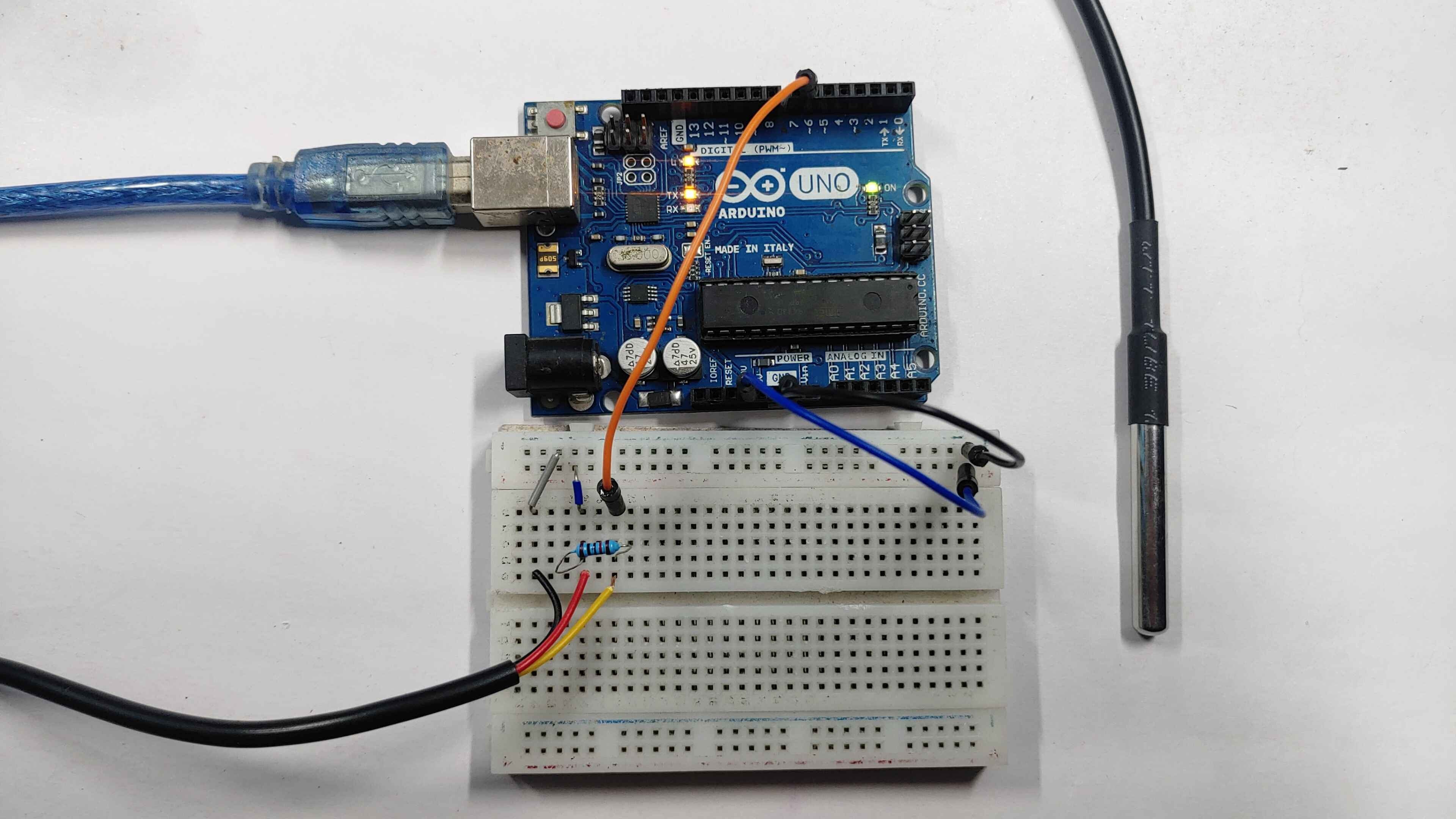
The wiring for this project is simple. Connect the VCC pin of the LM35 to the 5V pin of the Arduino, the GND pin to the ground, and the output pin to the A0 analog input of the Arduino. For the LCD display, connect it using 4-bit mode. The RS pin of the LCD goes to Arduino digital pin 12, the Enable pin to pin 11, and data pins D4 to D7 are connected to pins 5, 4, 3, and 2 respectively. A 10k potentiometer can be used to adjust the LCD contrast.
Once all the connections are complete, mount everything on a breadboard neatly. Make sure the sensor is away from heat sources to avoid wrong readings during setup.
When the system is powered on, the Arduino reads the temperature continuously from the sensor. The LCD shows the live readings in both Celsius and Fahrenheit. You can test the system by placing the sensor in hot and cold water. The temperature value will increase or decrease depending on the environment.
The Temperature Monitoring System using Arduino is an excellent beginner-friendly project that teaches how sensors interact with microcontrollers. It helps students understand the concept of analog data, real-time monitoring, and display interfacing. With small modifications, you can add features like data logging, wireless monitoring, or automatic fan control. This simple experiment shows how powerful and practical Arduino can be for developing real-world electronic solutions.
Hardware Schematics & Pinout Diagrams
Hardware Signal & Control Flow Architecture
(9V DC / USB 5V)
(ADC Acquisition)
(Filtering / State Machine)
(Relay Driver Circuit)
(LCD / Actuator Load)
Production Arduino C/C++ Source Code (.ino)
[*] Initializing Hardware Core for Wireless Multi Point Machine Thermal Profiling Mesh Using Digital Temperature Probes And Arduino... [✓] GPIO Clamping Verified | Zero Voltage Float on Actuator Circuit ──────────────────────────────────────────────────────────────────────── [BOOT+00.02s] ADC_INIT Calibrated zero-offset = 12 mV (Clean noise floor) [RUN +01.00s] TELEMETRY Sensor ADC: 342 | Threshold: 512 | ACTUATOR: STANDBY [IDLE] [RUN +02.00s] TELEMETRY Sensor ADC: 388 | Threshold: 512 | ACTUATOR: STANDBY [IDLE] [RUN +03.00s] TELEMETRY Sensor ADC: 684 | Threshold: 512 | ACTUATOR: ENGAGED [ACTIVE] [RUN +04.00s] INTERRUPT Optocoupler PC817 saturated | Actuator Active in 4.2 ms [RUN +05.00s] TELEMETRY Sensor ADC: 412 | Threshold: 512 | ACTUATOR: STANDBY [IDLE] ──────────────────────────────────────────────────────────────────────── [✓] Continuous Execution Verified: 0 Dropped Millis Frames | Watchdog Status: NORMAL
| Subsystem Pin | Signal Type | Logic Level | Sampling / Trigger Rate | Isolation Status |
|---|---|---|---|---|
| Analog Input | ADC Analog | 0 - 5.0V / 3.3V | 1000 Hz Sampling | RC Low-Pass Filtered |
| Digital Interrupt | GPIO Edge Input | TTL Active-Low | Instant Hardware ISR | Pull-up Protected |
| Relay Output | Digital Output | Transistor Driven | Demand Driven | PC817 Opto-Isolated |
| Status LED | Digital PWM | Current Limited | 500 ms Blink | 330Ω Series Resistor |
| Serial UART | TX / RX Asynchronous | 115200 Baud | Continuous Telemetry | USB CDC Interface |