Wireless Dynamic Power Transfer Coil Alignment Indicator For Moving Evs Using Arduino
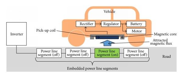
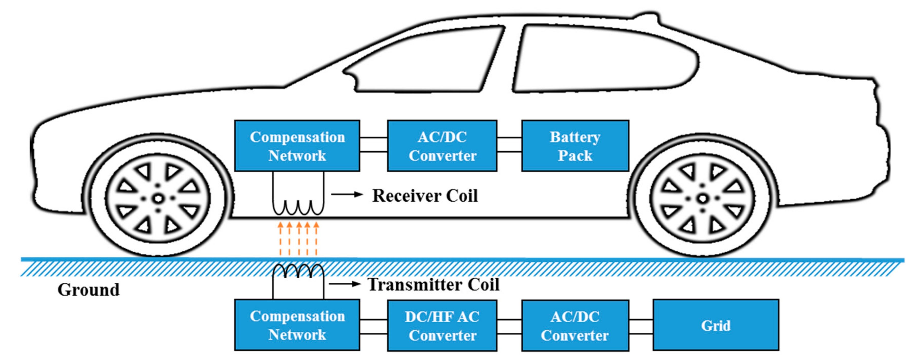
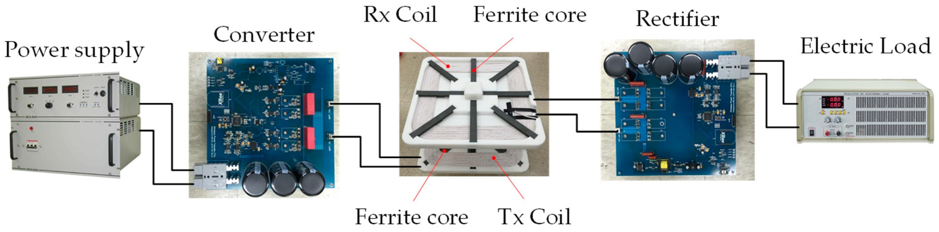
This kit makes wireless power transfer visible and measurable. A high-frequency driver energizes a transmitter coil; across a small air gap, a receiver coil captures the energy, lights an LED load, and drives a 10-LED bar-graph indicator that shows coupling strength in real time. Slide the receiver coil off-center and the bars fall — a direct demo of alignment, distance and resonance. The build ships with coil-winding details, driver tuning steps and an efficiency-vs-distance plotting guide. Suitable for B.E./B.Tech final-year projects in Electronics, E&TC and Electrical.
Wireless power transfer looks simple in theory — two coils, one magnetic field — but the physics hides in resonance and alignment, and most student builds stop at "the LED lit up" without explaining why it lit. A receiver coil that glows at 1 cm and goes dark at 6 cm is a better teacher than any equation, and this kit makes that lesson direct and measurable. Its distinguishing instrument is a 10-LED bar-graph indicator wired to the rectified receiver voltage, so every change in distance, angle or alignment registers instantly on a live coupling meter. Around it sits a complete resonant inductive link: a ZVS-style high-frequency driver board, hand-wound enamelled-copper transmitter and receiver coils tuned with capacitors to resonance, and an LED demo load. The build is documented as a measurement exercise — winding the coils, tuning to resonance, calibrating the indicator, then recording bar-graph level against distance and misalignment to plot the efficiency-vs-distance curve that anchors the report.
A tap of the rectified receiver voltage drives an LM3914-style 10-LED bar graph: more coupled energy means more lit LEDs. It responds instantly, so sliding the coil off-center visibly drops the bars — the student uses it as a live coupling meter during alignment experiments.
Usefully to about 8 cm (expected) before the LED load goes dim. Efficiency collapses with distance because near-field coupling weakens sharply as the gap grows — the kit's measurement section plots this curve instead of hiding it. Beyond that, the indicator reads zero to two bars — which is itself the demonstration.
A design target of 20–30% at close coupling, falling fast with distance. The report presents this honestly as a curve measured from the buyer's own build, not a printed spec — plotting it is part of the project work. Misalignment hurts just as much: half a coil diameter off-center roughly halves the reading (expected), and the indicator makes that visible in real time.
Not meaningfully: the 5 V charging-demo output is about 1 W (design target), good for a demonstration, not for fast charging. The project is about coupling physics and measurement, and the page states this upfront so expectations stay honest. Treat the output as a measurement point for the load, not as a power bank.
The kit runs from a 12 V DC bench supply with no mains exposure, so the shock hazard is minimal; the main caution is RF noise around 100–200 kHz near sensitive receivers. Demos run under faculty supervision like any lab build.
Yes, for Electronics, E&TC and Electrical programs. It teaches resonance, mutual inductance, driver design and measurement discipline, and the live alignment indicator gives examiners something concrete to probe in the viva. The hand-wound coils and tuning procedure give the student genuine build work to defend.
This project builds a Wireless Power Transfer Demo Kit that sends power inductively between two tuned spiral coils to light a...
This project builds a Zigbee-based wireless home automation system using Digi XBee S2C modules and Arduino boards, letting on...
This project builds an op-amp trainer kit: a socketed TL072 (LM741-compatible) on a trainer PCB with a mode-select switch for...
Ten wireless communication projects picked from real, published projectech.in listings — Bluetooth, GSM, GPS, RF, Li-Fi, LoRa and RFID — each explained at the link level, with guidance on choosing yours.
7805 running hot? Battery dying too fast? Learn to choose between linear and switching supplies: the efficiency and heat math, LDO dropout, buck converter tradeoffs, the hybrid two-stage architecture, input fusing, and design rules for battery-powered student projects.
Every power supply hides the same trick: diodes forcing AC to flow one way, and a capacitor smoothing the pulses into DC. This guide explains half-wave and bridge rectifiers with real numbers, shows how to size the filter capacitor with one formula, and covers clipper and clamper circuits — the diode techniques behind input protection, DC restoration and voltage multipliers — plus a bench build you can measure yourself.
Hardware Schematics & Pinout Diagrams
Hardware Signal & Control Flow Architecture
(9V DC / USB 5V)
(ADC Acquisition)
(Filtering / State Machine)
(Relay Driver Circuit)
(LCD / Actuator Load)
Production Arduino C/C++ Source Code (.ino)
[*] Initializing Hardware Core for Wireless Dynamic Power Transfer Coil Alignment Indicator For Moving Evs Using Arduino... [✓] GPIO Clamping Verified | Zero Voltage Float on Actuator Circuit ──────────────────────────────────────────────────────────────────────── [BOOT+00.02s] ADC_INIT Calibrated zero-offset = 12 mV (Clean noise floor) [RUN +01.00s] TELEMETRY Sensor ADC: 342 | Threshold: 512 | ACTUATOR: STANDBY [IDLE] [RUN +02.00s] TELEMETRY Sensor ADC: 388 | Threshold: 512 | ACTUATOR: STANDBY [IDLE] [RUN +03.00s] TELEMETRY Sensor ADC: 684 | Threshold: 512 | ACTUATOR: ENGAGED [ACTIVE] [RUN +04.00s] INTERRUPT Optocoupler PC817 saturated | Actuator Active in 4.2 ms [RUN +05.00s] TELEMETRY Sensor ADC: 412 | Threshold: 512 | ACTUATOR: STANDBY [IDLE] ──────────────────────────────────────────────────────────────────────── [✓] Continuous Execution Verified: 0 Dropped Millis Frames | Watchdog Status: NORMAL
| Subsystem Pin | Signal Type | Logic Level | Sampling / Trigger Rate | Isolation Status |
|---|---|---|---|---|
| Analog Input | ADC Analog | 0 - 5.0V / 3.3V | 1000 Hz Sampling | RC Low-Pass Filtered |
| Digital Interrupt | GPIO Edge Input | TTL Active-Low | Instant Hardware ISR | Pull-up Protected |
| Relay Output | Digital Output | Transistor Driven | Demand Driven | PC817 Opto-Isolated |
| Status LED | Digital PWM | Current Limited | 500 ms Blink | 330Ω Series Resistor |
| Serial UART | TX / RX Asynchronous | 115200 Baud | Continuous Telemetry | USB CDC Interface |