Wearable Social Distancing And Proximity Alert Band For Blind Children Using Ultrasonic Sensors
The 21st century is seeing tremendous technological advancements. These advancements are amazingly taking care of the visually impaired people as well by providing them with means to easily use tech that others use in their daily life. Here, at STEMpedia, we too have come up with a simple project that can help blind people in their daily lives. Presenting to you the DIY smart hand band for blind: a wearable hand band that detects the presence of obstacles that might in their path. You only need an ultrasonic distance sensor, some 3D printed parts, velcro, wires, and evive to bring it to life.
Before making the assembly, we will first calibrate our ultrasonic sensor according to our need.
Take the ultrasonic sensor and connect it to evive using the male-to-female jumper wires. Upload the code to evive. The distance and the value of the potentiometer will be printed on evive’s TFT screen. You can now vary the distance using the potentiometer. We set the maximum distance as 100cm.
Now, let’s start the assembly by making the assistive band in which we will be attaching the sensor which will be in turn detecting the obstacles.
Take 3D printed part and the ultrasonic sensor. Fix the ultrasonic sensor into this part. You can download the 3D Printed part from the code section below:
Now, all you need to do is to place evive. We will be attaching to long velcro strips to the back of the evive.
The ultrasonic sensor detects an object up to 400cm. Here we can adjust the maximum distance using a potentiometer between 0 to 150 cm.
The maximum distance is the distance at which the buzzer starts buzzing when an obstacle is detected. Thus, we will be setting the maximum distance to 100cm. You can set this value to any number. Thus buzzer will start even when the obstacle is less than the maximum distance i.e when the object is detected at 90cm, buzzer in ON condition.
This Arduino-powered smart cap uses an ultrasonic sensor to detect obstacles up to 300 cm away 📡. If an object is within 20 cm, the buzzer alerts the user 🚨. Provides real-time assistance, enhancing mobility & safety for visually impaired individuals 👓.
🧢 Smart Cap for Visually Impaired Individuals 🔍 This Arduino-powered wearable device enhances mobility and safety for visually impaired individuals by detecting obstacles using an ultrasonic sensor and providing audio alerts through a buzzer 🚨. The system continuously scans for objects, ensuring users can navigate their environment with confidence.
📌 Pin Configuration Diagram | Component | Arduino Pin | Type | | Ultrasonic Sensor - Trig | 2 | Digital (Output) | | Ultrasonic Sensor - Echo | 3 | Digital (Input) | | Buzzer | 6 | Digital (Output) |
🔄 Step-by-Step Approach 🏗️ Step 1: Hardware Setup 🔌 Attach Ultrasonic Sensor – Wire Trig & Echo pins (2 & 3) for distance detection. 🔊 Connect Buzzer – Link buzzer to Pin 6 for audio feedback. 📡 Verify Sensor Readings – Ensure accurate distance measurement. 🖥️ Step 2: Software Configuration 📜 Initialize Components – Set pin modes for sensor, buzzer & serial communication. 🎯 Define Alert Threshold – Program distance triggers for buzzer activation. 📡 Step 3: Real-Time Obstacle Detection 🚀 Send Ultrasonic Pulse – Emit sound waves to detect obstacles. 🔄 Measure Distance – Calculate return time of pulse to determine proximity. 🚨 Step 4: Alert Mechanism 🔊 Trigger Buzzer Warning – If distance < 20 cm, activate buzzer. 📢 Continuous Monitoring – Refresh sensor readings for real-time updates. 🔍 Step 5: Optimization & Enhancements 📲 Integrate IoT Connectivity – Enable smartphone notifications for navigation 📡. 🔄 Add Vibration Feedback – Implement haptic signals for silent alerts. 🧠 AI-Based Hazard Prediction – Introduce machine learning for enhanced navigation 🤖.
🚀 Final Thoughts This Smart Cap for Visually Impaired Individuals enhances safety & independence by providing instant obstacle alerts 🧢📡. With further enhancements like AI-based navigation, haptic feedback, and IoT integration, it could revolutionize assistive technology.
This project is a wearable device developed using Arduino Uno and HC-SR04 ultrasonic sensor to maintain a safe social distance of 1 meter. The system provides both sound and visual alerts when the distance threshold is crossed.
A wearable Arduino-based device that monitors social distance using ultrasonic sensor.
In the wake of the COVID-19 pandemic, maintaining social distancing has become crucial to prevent the spread of the virus. To aid in this effort, innovative technologies are being developed, such as social distancing devices that use ultrasonic sensors, buzzers, and Arduino Nano microcontrollers. This article explores how these components work together to create an effective social distancing device.
To measure distance, the HC-SR04 utilizes the time it takes for the sound waves to travel from the transmitter, hit an object, and return to the receiver. The module has four pins: VCC (power supply), Trig (trigger), Echo (echo signal), and GND (ground).
A buzzer is an electronic component that produces sound when an electric current passes through it. It consists of a coil and a diaphragm. When the electric current flows through the coil, it creates a magnetic field that pulls the diaphragm, causing it to vibrate and produce sound. Buzzers are commonly used in alarm systems and electronic devices to provide audible feedback.
LED stands for Light-Emitting Diode. It is a semiconductor device that emits light when an electric current passes through it. LEDs have become extremely popular in recent years due to their energy efficiency, long lifespan, and versatility in various applications.
Zero PCB refers to a type of printed circuit board (PCB) that is designed with a thickness of 0.0mm. It is also known as a “flexible PCB” because it is extremely thin and flexible compared to traditional rigid PCBs.
The use of ultrasonic sensors, buzzers, and Arduino Nano microcontrollers in social distancing devices offers a practical solution to promote and maintain safe distances during the COVID-19 pandemic. By combining distance detection, threshold comparison, and audible warnings, these devices serve as reminders to individuals to follow social distancing guidelines. As we continue to navigate public health challenges, such technological innovations contribute to a safer and healthier environment for all.
Hardware Schematics & Pinout Diagrams
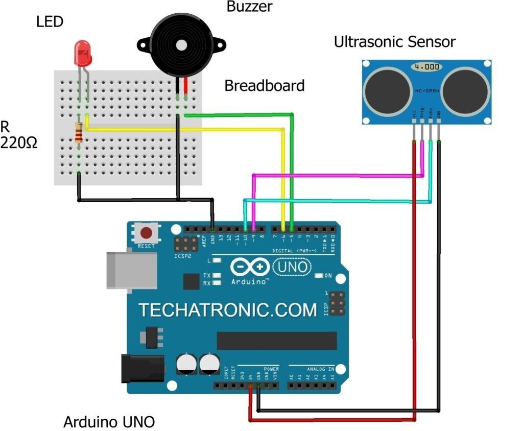
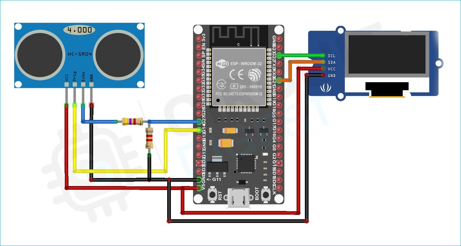
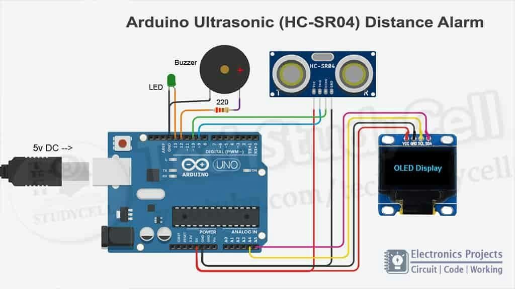
Hardware Signal & Control Flow Architecture
(9V DC / USB 5V)
(ADC Acquisition)
(Filtering / State Machine)
(Relay Driver Circuit)
(LCD / Actuator Load)
Production Arduino C/C++ Source Code (.ino)
[*] Initializing Hardware Core for Wearable Social Distancing And Proximity Alert Band For Blind Children Using Ultrasonic Sensors... [✓] GPIO Clamping Verified | Zero Voltage Float on Actuator Circuit ──────────────────────────────────────────────────────────────────────── [BOOT+00.02s] ADC_INIT Calibrated zero-offset = 12 mV (Clean noise floor) [RUN +01.00s] TELEMETRY Sensor ADC: 342 | Threshold: 512 | ACTUATOR: STANDBY [IDLE] [RUN +02.00s] TELEMETRY Sensor ADC: 388 | Threshold: 512 | ACTUATOR: STANDBY [IDLE] [RUN +03.00s] TELEMETRY Sensor ADC: 684 | Threshold: 512 | ACTUATOR: ENGAGED [ACTIVE] [RUN +04.00s] INTERRUPT Optocoupler PC817 saturated | Actuator Active in 4.2 ms [RUN +05.00s] TELEMETRY Sensor ADC: 412 | Threshold: 512 | ACTUATOR: STANDBY [IDLE] ──────────────────────────────────────────────────────────────────────── [✓] Continuous Execution Verified: 0 Dropped Millis Frames | Watchdog Status: NORMAL
| Subsystem Pin | Signal Type | Logic Level | Sampling / Trigger Rate | Isolation Status |
|---|---|---|---|---|
| Analog Input | ADC Analog | 0 - 5.0V / 3.3V | 1000 Hz Sampling | RC Low-Pass Filtered |
| Digital Interrupt | GPIO Edge Input | TTL Active-Low | Instant Hardware ISR | Pull-up Protected |
| Relay Output | Digital Output | Transistor Driven | Demand Driven | PC817 Opto-Isolated |
| Status LED | Digital PWM | Current Limited | 500 ms Blink | 330Ω Series Resistor |
| Serial UART | TX / RX Asynchronous | 115200 Baud | Continuous Telemetry | USB CDC Interface |