Voice Controlled Lighting And Curtain Automation System For Elderly Sufferers Of Reduced Mobility
In this home automation project using Arduino, we will use voice function to control home devices. This project is similar to home automation using Bluetooth. In that project, we used the S2 Terminal application however in this project we will use AMR_Voice Android application. This application is free and very easy to use. People of any age can control it by just speaking the commands. So let us begin!
In this voice-controlled home automation system, Arduino Uno is used as the brain of our circuit.
You can view the operations constituting the voice control home automation system in the block diagram below
In this section, we will explain the connections of the various components specified above with Arduino Uno to form the home automation system.
The HC-05 comes with multiple pins and indicators, which helps to control different operations and view their states through indicators. This pinout diagram provides indications of all pins.
However, we will use 4 of these pins to connect with Arduino. These include the VCC, GND, RX, and TX pins.
The connection of the HC-05 Bluetooth module with Arduino UNO is very easy as we will be using the serial communication interface that consists of two pins TX and RX. As you know, in order to communicate with the HC-05 Bluetooth module, we need to use a UART communication port of the Arduino board.
RX and TX pins of the module will be connected with the UART pins of Arduino UNO. Arduino Uno has a single UART interface found on pin 0 (RX0) and pin 1 (TX0).
The table below shows the connections that we will use to connect the two devices:
Recommended Reading: HC-05 Bluetooth Module Interfacing with Arduino with LED Control Example
We will use a 16×2 LCD in our project to display the states of the appliances. To connect a 16×2 LCD with Arduino we will require an additional 10k potentiometer as well.
We have a dedicated tutorial regarding interfacing 16×2 LCD display with Arduino with some example sketches. Have a look at it before proceeding further for a better understanding of the LCD.
Recommended Reading: 16×2 LCD Interfacing with Arduino – Explained with Example Codes
There are two types of pins on the whole 16×2 LCD module. Some pins are used to send to 16×2 LCD and some are command pins. In other words, every pin has a role in controlling a single pixel on the display.16 x 2 LCD has sixteen columns and two rows. That means, it can display sixteen characters per row and it has two such rows.
The diagram shows the pin configuration of a 16×2 LCD display. It has sixteen pins.
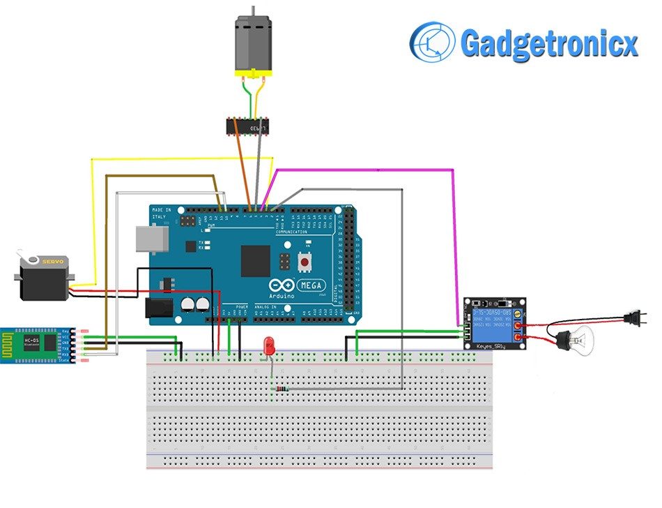
We are using the following connections as described below. Refer to the schematic diagram to have a clearer idea of the connections.
We have an Arduino library for easy communication between LCDs called the LiquidCrystal library. It is an inbuilt library by Arduino Adafruit version.
The relay module for Arduino is one of the most powerful applications for Arduino as it can be used to control both A.C and D.C devices by simply controlling the relay by giving 5V. A relay is basically a switch which is operated electrically by an electromagnet. A relay can be used to control high voltage electronic devices such as motors as well as low voltage electronic devices such as a light bulb or a fan.
Throughout this guide, we will use an android smartphone that will connect to our Arduino development board. So, make sure you have an android phone at hand.
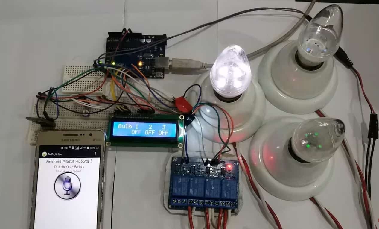
Open the application and speak the specified commands. The application sends the command to Bluetooth which is then received by Arduino which performs the described task. At the same time, the Arduino displays the status of the appliances on the LCD.
For demonstration purposes, we will use different colored bulbs: white, blue, and green.
Each command has its unique operations which are defined in code. You can change the commands according to your ease. Below is the list of commands that the user will speak to control the bulbs.
We will use Arduino IDE to program our Arduino board. Open your Arduino IDE and go to File > New to open a new file. Copy the code given below in that file and save it.
Next, we declare the Arduino pins that are connected with the LCD. To define connections, we use the following line of code. This line creates a LiquidCrystal object and lcd is a name of the object that we are going to use to call LCD functions. You can also use any other name.
Specify the Arduino pins connected with IN1, IN2 and IN3 of 4 Channel Relay Module. These pins will control white, blue and green bulbs.
Moreover, also specify the Arduino digital pins connected with TX and RX pins of the HC-05 module.
Also, we create an array of 15 characters called inSerial that we will use later on in the code to monitor the states of the bulbs.
Configure the pins connected with the bulbs and the TX pin as output pins and the RX pin as an input pin. This is done by using the pinMode function. Specify the pin as the first parameter and the mode as the second parameter.
Moreover, set the value of the pins connected with the three bulbs to HIGH by using digitalWrite function. Specify the pin as the first parameter and the value as the second parameter. This will ensure that all the bulbs are off initially.
Next, we use lcd.begin routine to define the size of an LCD. The first argument to this function is a number of rows and the second argument is a number of columns. For instance, this line declares the size as 16 columns and 2 rows. That means 16×2 size.
Print a series of messages on the LCD display with delays in between. Initially all the three bulbs are off hence it will be displayed on the LCD.
Inside the infinite loop we first check if serial data is available in the buffer. If data is found then the characters are added one by one to the array ‘inSerial’ using a while loop. Then we will call the Check_Protocol function with ‘inSerial’ as an argument inside it. This function will be responsible for controlling the bulbs by comparing the received data with a predefined string.
The Check_Protocol function takes in an array of characters as an argument inside it.
This function is responsible for controlling the bulbs by comparing the strings received in the buffer with a predefined string. In the first case, if the command ‘white on’ was sent, then the white bulb will turn ON. If the command ‘white off’ was sent, then the white bulb will turn OFF. Likewise, if the command ‘blue on’ was sent, then the blue bulb will turn ON. If the command ‘blue off’ was sent, then the blue bulb will turn OFF. Likewise, the green bulb will be controlled similarly with commands ‘green on’ and ‘green off’.
The LCD will display all the states of the three bulbs as they change at each command.
Make sure you choose the correct board and COM port before uploading your code to the board. Go to Tools > Board and select Arduino UNO. Next, go to Tools > Port and select the appropriate port through which your board is connected.
Click on the upload button to upload the code to the board. Installed this Andriod app on your smartphone. After you have uploaded your code to the development board and have installed the application on your smartphone, open the application and connect it with the HC-05 Bluetooth module. After pairing is completed. You can speak an appropriate command as defined in the code. As a result, the bulbs will light up in response. The LCD will also display the current state of the three bulbs.
Sir can you tell me the proper code i could not understand where it start and where it ends
Voice-controlled automation brings together electronics, wireless communication, and programming in a practical home project. Instead of manually switching appliances, a voice command can be converted into a wireless instruction and used to control relays connected to lights, fans, or other low-voltage loads. This guide explains how to build a voice controlled home automation Arduino project using a Bluetooth-based control system, including the components required, their connections, and the basic operating logic.
Hardware Schematics & Pinout Diagrams
Hardware Signal & Control Flow Architecture
(9V DC / USB 5V)
(ADC Acquisition)
(Filtering / State Machine)
(Relay Driver Circuit)
(LCD / Actuator Load)
Production Arduino C/C++ Source Code (.ino)
[*] Initializing Hardware Core for Voice Controlled Lighting And Curtain Automation System For Elderly Sufferers Of Reduced Mobility... [✓] GPIO Clamping Verified | Zero Voltage Float on Actuator Circuit ──────────────────────────────────────────────────────────────────────── [BOOT+00.02s] ADC_INIT Calibrated zero-offset = 12 mV (Clean noise floor) [RUN +01.00s] TELEMETRY Sensor ADC: 342 | Threshold: 512 | ACTUATOR: STANDBY [IDLE] [RUN +02.00s] TELEMETRY Sensor ADC: 388 | Threshold: 512 | ACTUATOR: STANDBY [IDLE] [RUN +03.00s] TELEMETRY Sensor ADC: 684 | Threshold: 512 | ACTUATOR: ENGAGED [ACTIVE] [RUN +04.00s] INTERRUPT Optocoupler PC817 saturated | Actuator Active in 4.2 ms [RUN +05.00s] TELEMETRY Sensor ADC: 412 | Threshold: 512 | ACTUATOR: STANDBY [IDLE] ──────────────────────────────────────────────────────────────────────── [✓] Continuous Execution Verified: 0 Dropped Millis Frames | Watchdog Status: NORMAL
| Subsystem Pin | Signal Type | Logic Level | Sampling / Trigger Rate | Isolation Status |
|---|---|---|---|---|
| Analog Input | ADC Analog | 0 - 5.0V / 3.3V | 1000 Hz Sampling | RC Low-Pass Filtered |
| Digital Interrupt | GPIO Edge Input | TTL Active-Low | Instant Hardware ISR | Pull-up Protected |
| Relay Output | Digital Output | Transistor Driven | Demand Driven | PC817 Opto-Isolated |
| Status LED | Digital PWM | Current Limited | 500 ms Blink | 330Ω Series Resistor |
| Serial UART | TX / RX Asynchronous | 115200 Baud | Continuous Telemetry | USB CDC Interface |