Visual Target Tracking Pan Tilt Gimbal Mechanism Driven By Arduino And Pixy Camera Interfacing
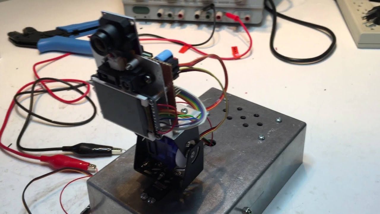
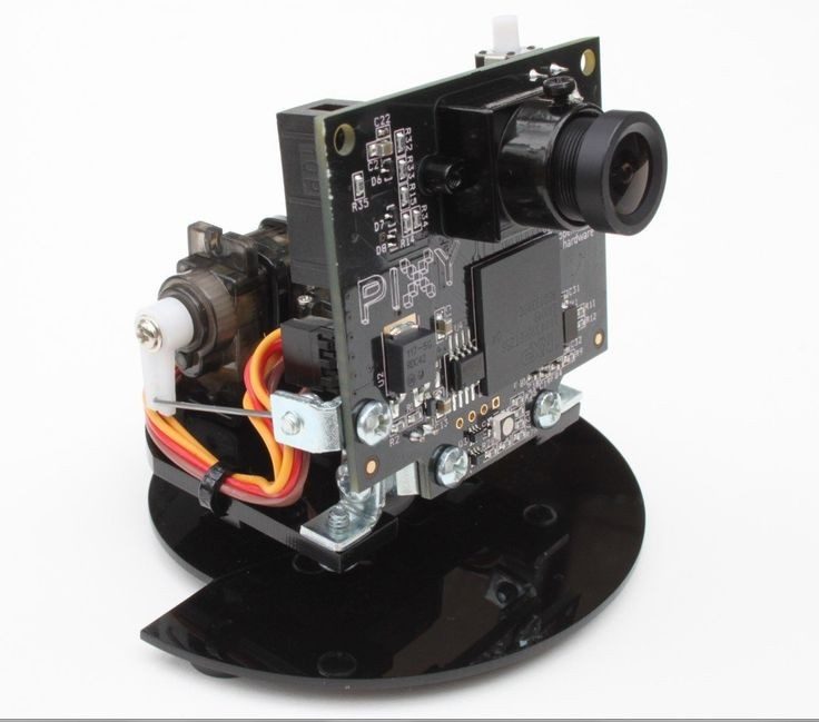
OK, you've assembled the pan/tilt mechanism and it looks cool, but it would look even cooler if it moved. One nice thing is that you don't need a battery to move the pan/tilt – the pan/tilt can use the USB cable for power, as long as the cable is 4 ft or shorter . (3 ft is common, and even better.) If you use a longer cable, there can be up to 1 volt of voltage drop along the cable, which is fine for Pixy, but the servos will malfunction. Also, before you run the pan/tilt demo, go ahead and teach Pixy an object if you haven't already.
We should also mention that the pan/tilt base needs to be anchored to the table somehow before running the demo. Use a couple pieces of tape, if you like – it doesn't take much – or use a binder clip to attach the pan/tilt base to a magazine. If you don't anchor the base, the base will tend to rotate under Pixy, leaving Pixy more or less stationary (and we want Pixy to move/rotate!)
Note: if you're having trouble making the pan/tilt run properly, here's a handy troubleshooting page.
When Pixy first powers up, you'll notice that the LED turns on (white) for about 1 second, then flashes, then turns off. What's really happening is Pixy is asking you which program you want to run. Currently, Pixy ships with two programs:
So, power up Pixy, and when the LED turns on (white), hold down the button. The LED will turn white then red, white then red, etc. If you release the button when the LED is white, you will select the default tracking program. If you release the button when the LED is red you will select the pan/tilt demo. So do that – release the button when the LED is red. The LED will flash red a couple times which means “running program 2!”
A quick note on program selection – normally, upon power up, if you don't press the button, Pixy “times-out” and just runs the default program, which is the tracking program, but you can configure which program is the default program from the PixyMon Configure Dialog .
If you're running PixyMon, you can run the demo (or any other program) at any time by selecting it in the Action menu. In particular, select Action➜Run the pan/tilt demo .
Pixy should then track your object and plot the detected objects in the video window. Yay!
For example, try changing the Pan P gain (pan axis proportional gain) from 500 to 50, then hit Apply . Or increase the gains and see what happens. Many times, increasing the gains results in some erratic behavior, but don't worry – you won't damage anything. If you want to go back to the default values select Action➜Restore default parameters . There is more information here .
You can have your Arduino perform pan/tilt tracking too. The Arduino reads in the object blocks and calculates the positions of the pan and tilt servos and sends the calculated positions back to Pixy, and Pixy then updates the servo positions. This is great for getting your Pixy and Arduino better acquainted and getting them both collaborating in some kind of application that you write.
This requires that you run the “default” Pixy program – not the pan/tilt demo program. The default program is the program Pixy runs upon power-up by default without pressing any buttons. You can also run the default program by selecting it in the Actions menu in PixyMon.
OK, start by getting the latest Arduino-Pixy code , and install as described here . Load the pantilt demo by selecting it in File➜Examples➜Pixy➜pantilt in the Arduino IDE. Upload it, and as long as Pixy is running the default program, you should start seeing the pan/tilt move to track any object that matches signature 1. (Note, you'll need to teach Pixy an object if you haven't done so already.)
You can also play with the Arduino code, such as changing the proportional and derivative gains.
Here, 300 is the proportional gain and 500 is the derivative gain for the pan servo. Likewise, 500 and 700 are the proportional and derivative gains for the tilt axis. Try reducing the proportional gain in half and see what happens.
With a little tweaking and modifying, this code can become a “chasing” instead of a “tracking” algorithm. That is, instead of calculating servo positions your Arduino can calculate motor speeds. So now your Pixy-Arduino robot creation can chase a ball, toy, etc. Adafruit created just such a robot, and they describe how to build and program one here .
No coding required. Please download the CASP project files from Gitlab repository https://gitlab.com/tul.ishwa/projects
Hardware Schematics & Pinout Diagrams

Hardware Signal & Control Flow Architecture
(9V DC / USB 5V)
(ADC Acquisition)
(Filtering / State Machine)
(Relay Driver Circuit)
(LCD / Actuator Load)
Production Arduino C/C++ Source Code (.ino)
[*] Initializing Hardware Core for Visual Target Tracking Pan Tilt Gimbal Mechanism Driven By Arduino And Pixy Camera Interfacing... [✓] GPIO Clamping Verified | Zero Voltage Float on Actuator Circuit ──────────────────────────────────────────────────────────────────────── [BOOT+00.02s] ADC_INIT Calibrated zero-offset = 12 mV (Clean noise floor) [RUN +01.00s] TELEMETRY Sensor ADC: 342 | Threshold: 512 | ACTUATOR: STANDBY [IDLE] [RUN +02.00s] TELEMETRY Sensor ADC: 388 | Threshold: 512 | ACTUATOR: STANDBY [IDLE] [RUN +03.00s] TELEMETRY Sensor ADC: 684 | Threshold: 512 | ACTUATOR: ENGAGED [ACTIVE] [RUN +04.00s] INTERRUPT Optocoupler PC817 saturated | Actuator Active in 4.2 ms [RUN +05.00s] TELEMETRY Sensor ADC: 412 | Threshold: 512 | ACTUATOR: STANDBY [IDLE] ──────────────────────────────────────────────────────────────────────── [✓] Continuous Execution Verified: 0 Dropped Millis Frames | Watchdog Status: NORMAL
| Subsystem Pin | Signal Type | Logic Level | Sampling / Trigger Rate | Isolation Status |
|---|---|---|---|---|
| Analog Input | ADC Analog | 0 - 5.0V / 3.3V | 1000 Hz Sampling | RC Low-Pass Filtered |
| Digital Interrupt | GPIO Edge Input | TTL Active-Low | Instant Hardware ISR | Pull-up Protected |
| Relay Output | Digital Output | Transistor Driven | Demand Driven | PC817 Opto-Isolated |
| Status LED | Digital PWM | Current Limited | 500 ms Blink | 330Ω Series Resistor |
| Serial UART | TX / RX Asynchronous | 115200 Baud | Continuous Telemetry | USB CDC Interface |