Vehicle Rollover Crash Emergency Beacon With Satellitecellular GPS Uplink Via Arduino
Road accidents are one of the leading causes of death worldwide. A major challenge is the delay in emergency response—victims often cannot make distress calls due to injury or shock, resulting in precious time being lost.
Our project, Automatic Vehicle Accident Detector , addresses this problem by creating an embedded system that detects accidents in real time and automatically sends alerts with GPS coordinates to emergency contacts. This reduces response time and increases the chances of survival.
The system integrates multiple sensors and communication modules, coordinated by a central microcontroller.
This project demonstrates how embedded systems + IoT can solve real‑world safety challenges. By automating emergency alerts and providing precise GPS data, we significantly reduce rescue response times.
🚗Embedded system for real-time vehicle accident detection and emergency alerting using Arduino, MPU6050, GPS, and GSM modules. Designed to reduce rescue response time and improve road safety.
The GPS Vehicle Accident Detection using Arduino is an intelligent system designed to enhance road safety through real-time accident detection and immediate emergency response. The system continuously monitors vehicle dynamics and location, automatically triggering an alert to predefined emergency contacts when a potential accident is detected.
Real-Time Detection: Uses an ADXL335 accelerometer to detect sudden impacts or rapid deceleration in X, Y, and Z dimensions. Precise Location Tracking: Integrates a NEO-6M GPS module to provide exact vehicle coordinates. Automated Alert System: Employs a SIM900 GSM module to send SMS alerts with GPS coordinates to emergency services and family members. Driver Feedback: Features a 16x2 LCD display to show system status, readiness, and real-time GPS data to the driver.
Arduino UNO: The central processing unit coordinating all sensors and modules. ADXL335 Accelerometer: Detects movement changes and converts them into signals for the Arduino. NEO-6M GPS Module: Pinpoints precise coordinates. SIM900 GSM Module: Enables SMS communication for alerts. 16x2 LCD Display: Provides a user interface for status updates.
Arduino IDE: Used for writing, compiling, and uploading code. Arduino Libraries: * TinyGPS++: For GPS module interfacing. * SoftwareSerial: For serial communication with multiple modules. * LiquidCrystal: For LCD display control. Proteus: Simulation software for circuit design and testing.
Initialization: The system initializes the GSM module and LCD display upon startup. Monitoring: The accelerometer continuously tracks vehicle movement for significant changes or impacts. Detection: If an accident threshold is met, the system retrieves current GPS coordinates. Alerting: An SMS containing the accident details and location is sent to predefined contacts. Feedback: Real-time status and coordinates are displayed on the LCD.
Emergency Response: Direct alerting for medical services to reduce response time during the "golden hour". Fleet Management: Real-time safety monitoring for commercial vehicles. Public Transit: Passenger safety monitoring for buses and taxis. Personal Safety: Individual car owner notification system for family and emergency contacts.
Arduino-based smart accident detection system using GPS, GSM, and ADXL335 accelerometer to detect vehicle crashes and automatically send real-time location alerts via SMS to emergency contacts, improving response time and road safety.
Car accident location – In this tutorial, we are going to make our own car accident detection unit which can be easily fitted inside the DashBoard or bonnet of the car. Arduino GPS car accident location tracking system is completely based on the Neo 6m GPS module and SIM900A gsm module. The Arduino GPS car accident location tracking system can be used throughout the world.
This article is sponsored by Wellpcb . Wellpcb is one of the top PCB’s manufacturing companies; they offer great quality and service. You can test their PCB quality only at 5 dollars for 5 PCB’s. You can ask for the price details by simply clicking on the PCB online quote, enter your PCB specifications, and click price. Once you are satisfied with their pricing then you can upload your Gerber files. Also, check out their other website ourpcb .
In the Car Accident Location tracking system, limit switches are used to detect if the car is hit. If the Car is hit a message is sent to the concerned person. The Cell Phone number used in the programming can be updated at any time.
For the Detailed step by step explanation, you can watch a Video Tutorial available at the end.
This is the GSM module that I will be using in this tutorial, in the market we have different types of GSM modules, the one I will be using today is sim900A, the same code is also tested on sim900D, so if you want you can also use sim900D.
If you are from Pakistan, Bangladesh or India make sure you purchase the unlocked version of the sim900A. This GSM sim900A module the one we will be using in this tutorial, as you can see on the screen has no Onboard voltage regulator, so be careful while applying the voltage. Ideal voltage for this GSM module is 4.7v but you can also connect it with the 5v adaptor.
As the ideal voltage for this gsm module is 4.7v to 5volts, so any voltage above this can damage the gsm module. If you don’t have the regulated 5v adaptor then you can also use an lm317t adjustable voltage regulator. I have a very detailed tutorial on this.
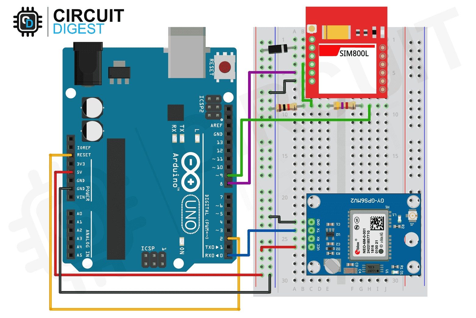
As you can see sim900A module has so many pins that are clearly labeled but we will be using only 5 of these pins, the power supply pins, GND, Rxd 5v, and txd 5v. The GND of the gsm sim900A module will be connected with the Arduino GND, TXD of the gsm sim900A will be connected with the Arduino pin7 and finally, the RXD of the gsm sim900A module will be connected with the Arduino pin8.
This is the Neo-6M GPS module that we gonna be using in this Tutorial. This GPS module can be interfaced with the Arduino using VCC, rx, tx, and gnd. For the easy interfacing, we will need to solder 4 wires with this Neo 6M GPS module. For the Soldering watch Video Tutorial .
The Neo 6M GPS module needs 3 to 5v. I will use the Arduino’s 5v and its default baud rate is 9600 which we will be using in the programming.
This is the complete circuit diagram of the Arduino GPS car accident location tracking system.
This schematic is designed in cadesoft eagle, if you want to learn how to make schematics and pcb’s then you can watch my tutorials visit my YouTube channel “ Electronic Clinic ”. The Neo-6MGPS and gsm sim900A modules interfacing with Arduino is very simple. As you can see in the circuit diagram the VCC of the GPS module is connected with 5v, Rx will be connected with pin3 of the Arduino, tx will be connected with pin2 of the Arduino and Gnd will be connected with the Arduino GND.
tx of the sim900A is connected with pin7 of Arduino, Rx of the sim900A is connected with pin8 of Arduino and is connected with the GND of Arduino. A power supply is connected with sim900A ideal voltage is 4.7v to 5v.
The limit switch is connected with pin4 of the Arduino, so when the limit switch is activated it will give 0 zero “gnd” as a signal to the Arduino this signal means that the car is hit.
Hardware Schematics & Pinout Diagrams

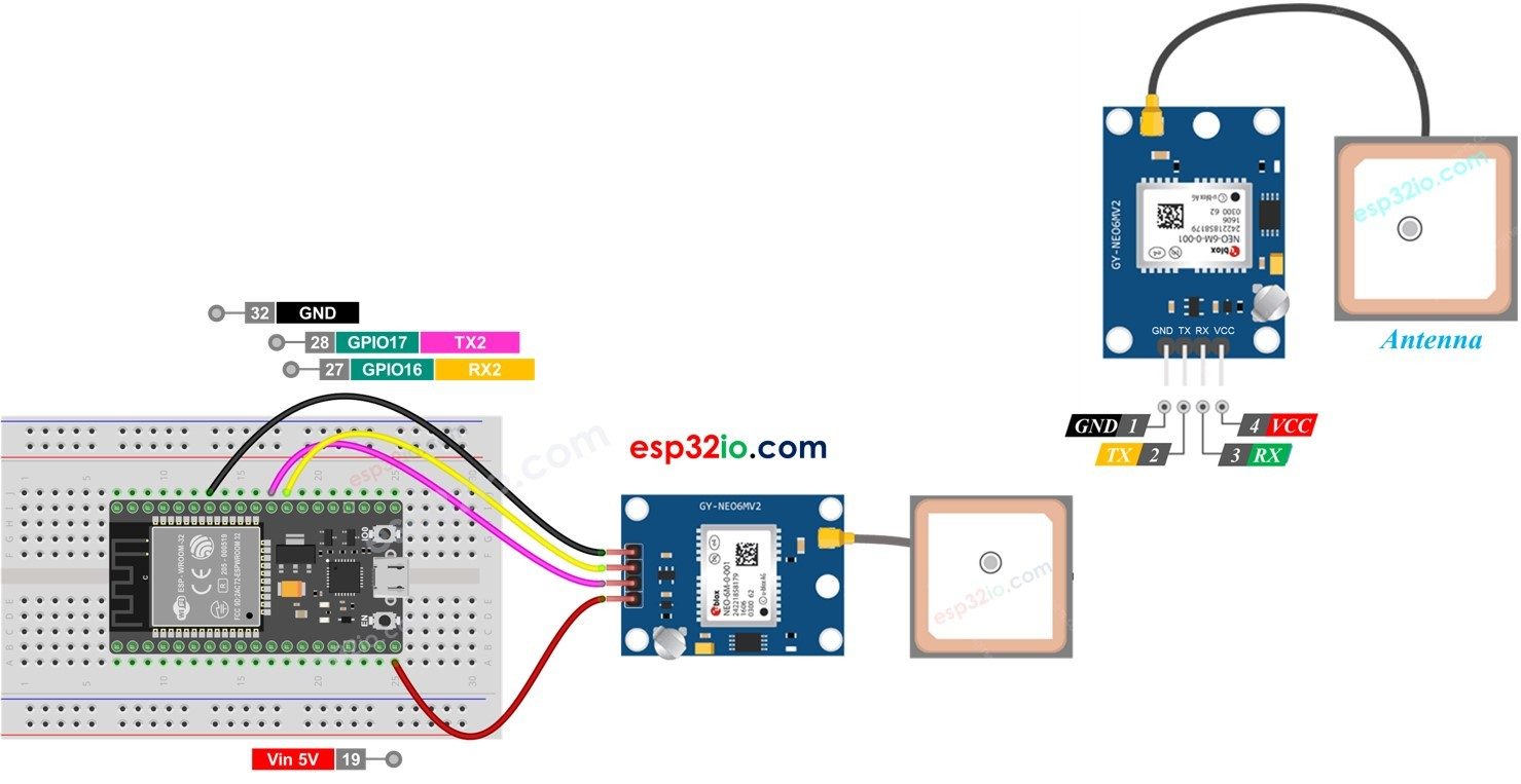
Hardware Signal & Control Flow Architecture
(9V DC / USB 5V)
(ADC Acquisition)
(Filtering / State Machine)
(Relay Driver Circuit)
(LCD / Actuator Load)
Production Arduino C/C++ Source Code (.ino)
[*] Initializing Hardware Core for Vehicle Rollover Crash Emergency Beacon With Satellitecellular GPS Uplink Via Arduino... [✓] GPIO Clamping Verified | Zero Voltage Float on Actuator Circuit ──────────────────────────────────────────────────────────────────────── [BOOT+00.02s] ADC_INIT Calibrated zero-offset = 12 mV (Clean noise floor) [RUN +01.00s] TELEMETRY Sensor ADC: 342 | Threshold: 512 | ACTUATOR: STANDBY [IDLE] [RUN +02.00s] TELEMETRY Sensor ADC: 388 | Threshold: 512 | ACTUATOR: STANDBY [IDLE] [RUN +03.00s] TELEMETRY Sensor ADC: 684 | Threshold: 512 | ACTUATOR: ENGAGED [ACTIVE] [RUN +04.00s] INTERRUPT Optocoupler PC817 saturated | Actuator Active in 4.2 ms [RUN +05.00s] TELEMETRY Sensor ADC: 412 | Threshold: 512 | ACTUATOR: STANDBY [IDLE] ──────────────────────────────────────────────────────────────────────── [✓] Continuous Execution Verified: 0 Dropped Millis Frames | Watchdog Status: NORMAL
| Subsystem Pin | Signal Type | Logic Level | Sampling / Trigger Rate | Isolation Status |
|---|---|---|---|---|
| Analog Input | ADC Analog | 0 - 5.0V / 3.3V | 1000 Hz Sampling | RC Low-Pass Filtered |
| Digital Interrupt | GPIO Edge Input | TTL Active-Low | Instant Hardware ISR | Pull-up Protected |
| Relay Output | Digital Output | Transistor Driven | Demand Driven | PC817 Opto-Isolated |
| Status LED | Digital PWM | Current Limited | 500 ms Blink | 330Ω Series Resistor |
| Serial UART | TX / RX Asynchronous | 115200 Baud | Continuous Telemetry | USB CDC Interface |