Vehicle Over Height Warning And Automated Diverting Signaler Before Low Clearance Urban Bridges
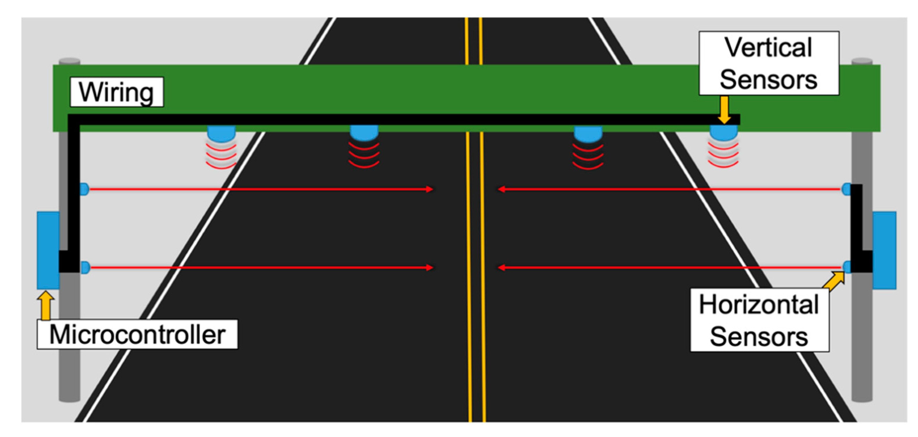
This circuit can be used to detect big over-height vehicle moving towards bridges, tunnel entrances and overhead structures, and warn the drivers. It can be developed for monitoring such a vehicle approaching, say, a bridge at night.
The vehicle detection system uses an infrared ( IR ) sensor to monitor the vehicle. An audio-visual alarm is activated when the over-height vehicle is detected by the system.
For example, a truck loaded with hazardous gases colliding with an overhead bridge can be dangerous. If a vehicle is too high to safely pass under the bridge, a sensor triggers an alarm placed at a distance ahead on the route. The alarm warns the driver to alter the course or stop before colliding with the overhead structure.
The circuit diagram of the vehicle detection system is shown in Fig. 1. It has an Arduino Uno board , IR proximity sensor module, 16×2 LCD (LCD1), piezo buzzer, preset (10-kilo-ohm), 9V battery and LED (LED1).
This module incorporates an IR transmitter and an IR receiver/detector in one package (Fig. 2). It transmits an IR beam continuously. Whenever an object or over-height vehicle is detected, the IR beam reflected from the object/vehicle is detected by the inbuilt IR receiver.
When the reflected IR beam is detected, the vehicle detection system generates an audio-visual alert informing the driver to stop the vehicle, as it may not be safe to continue. LED1 is used as a visual alert whenever an over-height vehicle is detected. Sensing range is adjustable with an inbuilt variable resistor in the IR module.
Arduino Uno that has an ATmega328 microcontroller (MCU) is used in the project. It consists of 14 digital input/output (I/O) pins, six analogue inputs, 16MHz crystal oscillator, USB connection, power jack, ICSP header and reset button. Output of the sensor module is analogue. It gets converted to digital through the inbuilt A/D converter of Arduino Uno.
A 10-kilo-ohm preset (VR1) is a three-legged electronic component used to vary the resistance in a circuit. Here, it is used to control the contrast of the LCD.
A 16-pin JHD162A LCD module is used in this project as a warning display. It is a two-lines and 16-characters LCD module, which can be replaced with a large LCD display (with some modifications in the circuit) for actual use.
Programming of Arduino Uno is done using Arduino IDE software. The program (vehicle_detection.ino) is written in Arduino programming language.
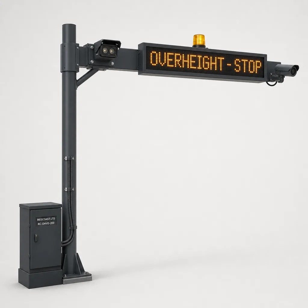
Make connections as per the circuit diagram. If an object or vehicle is not detected by the sensor, ‘Path is clear’ message is displayed on LCD1. If a vehicle is detected, the message reads as ‘Please Stop!!’ At the same time LED1 glows and the buzzer sounds an alarm (Fig. 3). The circuit can be wired on a breadboard with jumper wires for testing.
This vehicle detection system can be implemented using a laser sensor, speaker and bigger display, instead of a proximity sensor, buzzer and 16×2 LCD, respectively. The sensor and display should be installed along the path of the vehicle, before it approaches the bridge, so that the driver gets notified of the warning message well in time.
Navpreet Singh Tung is an assistant professor and project coordinator in the department of electrical engineering at Bhutta Group of College, Punjab
Can I get to know how can we make a working model of this project….like where to attach the lcd screen ….the detector..and Arduino along with the small representation with toy vehicles and an overhead bridge? I need a idea over this ….can you please help.??
The author Navpreet Singh Tung replies: Sensor system along with arduino must be attached on the roof of vehicle at front side in proper package with opening for sensor on front side to detect any obstacle in front of vehicle at height like bridge,cable etc. LCD must be inside vehicle near driver seat. Appropriate size of wires can be connected with the system. Size of entire project including packging depends on the size of toy. Rest depends on the type and design of toy. Accordingly, system can be adusted.
Thanks for this project. I want to try it but I cant access the source folder you uploaded. can you please forward it to my email, I’ll appreciate. My email is [email protected] Thank you.
Please download source code from here : http://efy.efymag.com/admin/issuepdf/Warning%20system%20for%20overheight%20vehicle.rar
This guide explains how to build and implement an Arduino-based height detection system at a tunnel entrance. The system detects over-height vehicles by monitoring an infrared (IR) beam. When a vehicle blocks the IR beam, a red LED illuminates and the LCD display shows the word “STOP” to prevent safety hazards. In the absence of blockage, the green LED remains active and the display indicates a clear path. This project involves careful planning of both the electronic circuit and the software logic using the Arduino IDE. Detailed wiring instructions, a circuit diagram, and annotated code examples are provided to help you successfully build the system.
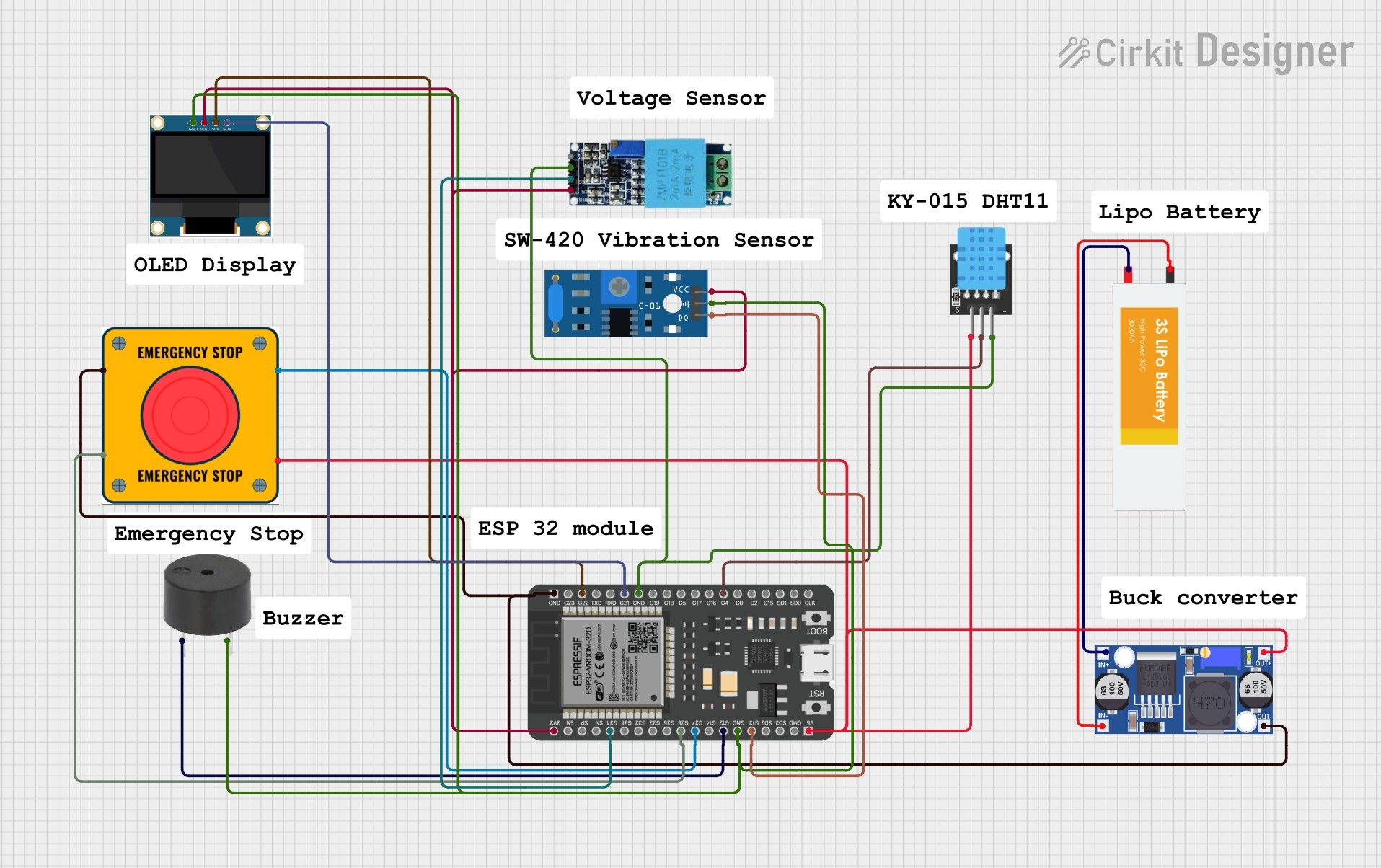
The circuit involves connecting the IR sensor, LEDs, and LCD display to the Arduino. Below is a detailed wiring guide along with a simplified diagram. Although a photo is recommended for clarity, the diagram below serves as a reference to help you correctly connect the components.
The following Arduino sketch is designed to implement the height detection behavior. The code checks the IR receiver’s output to determine whether the IR beam is blocked by an over-height vehicle. If the beam is interrupted, the code turns on the red LED and the LCD displays "STOP". Otherwise, it keeps the green LED on and displays a safe message on the LCD.
The program starts by including the necessary libraries: LiquidCrystal_I2C for handling the LCD, and Wire for I2C communication. This ensures that the LCD can easily be connected and controlled using just two data lines (SDA and SCL).
Each component is assigned a digital pin. The IR receiver’s output is on digital pin 2. Two digital pins are dedicated for LED output – one for the green LED and one for the red LED. An additional pin is optionally used for a piezo buzzer to generate an audible warning when the beam is blocked.
The setup function initializes the LCD and sets the correct pin modes (input for the IR receiver, output for LEDs and buzzer). The green LED is switched on to indicate that the path is clear, while the red LED remains off. A short delay allows the system to display an initial boot message before transitioning into a ready state.
The loop function continuously monitors the IR receiver. When the IR beam is interrupted (detected by a LOW state), the system responds by turning off the green LED and activating the red LED. The LCD then displays the word “STOP”, and if you have connected a buzzer, it issues a tone at 1000 Hz to alert nearby personnel. If the beam is uninterrupted, the system resets to a “clear” state by displaying "All Clear" on the LCD and reactivating the green LED.
While photos of the actual build can be extremely helpful, you can also refer to the following schematic diagram to visualize the circuit connections:
After setting up the circuit and uploading the code to your Arduino board, perform the following tests:
Depending on environmental conditions (lighting, distance, etc.), you may need to calibrate the sensitivity of your IR sensor. Adjust your positioning or add a comparator in the code if the sensor readings fluctuate. Additionally, check the alignment of the transmitter and receiver periodically to maintain system accuracy.
While the core system meets the primary objective of detecting over-height vehicles, you might consider some additional enhancements:
Since the system is intended for operational safety at critical infrastructure points, ensure that all components are securely housed in a weather-proof enclosure if deployed outdoors. Regular maintenance and calibration are key to reducing false positives or negatives. Always test the system under different conditions to ensure reliable performance.
Incorrect positioning of the IR transmitter and receiver is the most common issue. If the system does not detect vehicles reliably:
Utilize the Serial Monitor to print sensor values and debug the logic. Verify that computed sensor readings correlate with physical observations. Adjust the threshold values in the code, if necessary, to optimize system response.
For more detailed guidance and community projects, please refer to the following resources:
To deepen your understanding or explore related projects, consider these searches:
Hardware Schematics & Pinout Diagrams
Hardware Signal & Control Flow Architecture
(9V DC / USB 5V)
(ADC Acquisition)
(Filtering / State Machine)
(Relay Driver Circuit)
(LCD / Actuator Load)
Production Arduino C/C++ Source Code (.ino)
[*] Initializing Hardware Core for Vehicle Over Height Warning And Automated Diverting Signaler Before Low Clearance Urban Bridges... [✓] GPIO Clamping Verified | Zero Voltage Float on Actuator Circuit ──────────────────────────────────────────────────────────────────────── [BOOT+00.02s] ADC_INIT Calibrated zero-offset = 12 mV (Clean noise floor) [RUN +01.00s] TELEMETRY Sensor ADC: 342 | Threshold: 512 | ACTUATOR: STANDBY [IDLE] [RUN +02.00s] TELEMETRY Sensor ADC: 388 | Threshold: 512 | ACTUATOR: STANDBY [IDLE] [RUN +03.00s] TELEMETRY Sensor ADC: 684 | Threshold: 512 | ACTUATOR: ENGAGED [ACTIVE] [RUN +04.00s] INTERRUPT Optocoupler PC817 saturated | Actuator Active in 4.2 ms [RUN +05.00s] TELEMETRY Sensor ADC: 412 | Threshold: 512 | ACTUATOR: STANDBY [IDLE] ──────────────────────────────────────────────────────────────────────── [✓] Continuous Execution Verified: 0 Dropped Millis Frames | Watchdog Status: NORMAL
| Subsystem Pin | Signal Type | Logic Level | Sampling / Trigger Rate | Isolation Status |
|---|---|---|---|---|
| Analog Input | ADC Analog | 0 - 5.0V / 3.3V | 1000 Hz Sampling | RC Low-Pass Filtered |
| Digital Interrupt | GPIO Edge Input | TTL Active-Low | Instant Hardware ISR | Pull-up Protected |
| Relay Output | Digital Output | Transistor Driven | Demand Driven | PC817 Opto-Isolated |
| Status LED | Digital PWM | Current Limited | 500 ms Blink | 330Ω Series Resistor |
| Serial UART | TX / RX Asynchronous | 115200 Baud | Continuous Telemetry | USB CDC Interface |