Tired Using Audio Ingestion
Master Arduino speaker configuration with our guide on piezo buzzers, I2S DAC amplifiers, and PWM audio. Includes wiring diagrams and code examples.
Configuring an Arduino speaker setup goes far beyond simply connecting a buzzer to a digital pin. Whether you are building a retro synthesizer, an IoT device with voice alerts, or a high-fidelity audio logger, the microcontroller's native digital-to-analog capabilities dictate your hardware choices. Standard 8-bit AVR boards like the Arduino Uno lack a true DAC, relying instead on Pulse Width Modulation (PWM) or external Digital-to-Analog Converters (DACs). Meanwhile, modern 32-bit boards like the ESP32 or Arduino Nano RP2040 Connect feature native I2S (Inter-IC Sound) interfaces capable of driving high-quality audio amplifiers.
This configuration guide details the exact wiring, component selection, and software parameters required to drive various Arduino speaker types in 2026, moving from basic piezo alerts to CD-quality I2S audio synthesis.
Before writing a single line of code, you must match your transducer and amplifier topology to your board's processing architecture. Below is a comparative breakdown of standard Arduino speaker configurations, including approximate 2026 component pricing and ideal use cases.
Piezo transducers are highly capacitive loads. When driven directly by an ATmega328P GPIO pin, the rapid voltage transitions can cause electromagnetic interference (EMI) and ghost-triggering on adjacent analog inputs. Furthermore, when the PWM signal stops, the piezo can retain a charge, causing a faint, continuous humming or clicking sound.
To configure a passive piezo speaker correctly, you must place a 1kΩ to 10kΩ pull-down resistor in parallel with the piezo element. This bleeds off residual charge the moment the GPIO pin goes LOW, ensuring absolute silence between tones. Wire the positive lead of the piezo to a PWM-capable pin (e.g., Pin 8) and the negative lead to GND, with the resistor bridging the two leads.
For software configuration, the native tone function is the standard approach. However, be aware of hardware timer conflicts. On the ATmega328P, the tone function hijacks Timer2. This completely disables PWM functionality on Pins 3 and 11 while a tone is playing. If your project requires simultaneous motor control via PWM and audio alerts, you must either use an external 555 timer circuit for the audio or migrate to a board with more hardware timers, like the Arduino Mega 2560.
For projects requiring WAV file playback, text-to-speech, or high-quality synthesizer output, I2S is the mandatory protocol. The Adafruit MAX98357A I2S Class-D Amplifier is the industry standard for makers, integrating a DAC and a 3.2W amplifier into a single breakout board.
I2S requires three shared clock/data lines, plus power. Unlike analog audio, I2S is a digital bus, meaning wire length and signal integrity matter. Keep your I2S traces under 10cm to prevent clock jitter.
Modern ESP32 Arduino cores utilize the ESP32-audioI2S or the official I2S.h library. When configuring the I2S driver in your setup loop, you must define the DMA (Direct Memory Access) buffer count. Setting dma_buf_count = 8 and dma_buf_len = 64 provides a stable audio stream without consuming excessive SRAM. If you experience audio stuttering during Wi-Fi operations, increase the DMA buffer count to 12 to absorb network interrupt latencies.
If you are constrained to an 8-bit AVR microcontroller but need better audio than a square-wave piezo, you can use high-frequency PWM combined with a low-pass RC (Resistor-Capacitor) filter. This technique is heavily utilized by the Mozzi audio synthesis library , which configures the ATmega328P's Timer 1 to run at an ultrasonic 32,768 Hz PWM frequency, pushing the carrier noise far above the human hearing range.
To strip the 32kHz PWM carrier wave and leave only the audible audio envelope, you must build a hardware low-pass filter. The cutoff frequency ($f_c$) is calculated as $1 / (2 \pi R C)$.
This specific 1kΩ/100nF combination yields a cutoff frequency of approximately 1.59 kHz. While this rolls off high treble frequencies, it effectively eliminates PWM switching noise. For full-range audio (up to 10kHz), use a 150Ω resistor and a 100nF capacitor, but be aware that the lower impedance will draw more current from the GPIO pin.
Even with correct wiring, audio configurations frequently suffer from analog artifacts. Here is how to diagnose and resolve the most common issues encountered in the field.
Symptom: A loud 50Hz/60Hz hum or high-frequency whine that changes pitch when the microcontroller processes data. Cause: Class-D amplifiers like the PAM8403 or MAX98357A switch rapidly at high currents. If the amplifier's ground is shared on the same breadboard rail as the microcontroller's logic ground, switching noise injects directly into the MCU's reference voltage. Solution: Implement a star-ground topology. Run a dedicated, thick ground wire directly from the power supply's negative terminal to the amplifier's GND pin, and a separate wire to the Arduino's GND. Do not daisy-chain grounds.
Symptom: Harsh, crackling audio during loud transients. Cause: Impedance mismatch or insufficient current delivery. A standard USB port provides only 500mA. If your speaker is rated for 4Ω and the amplifier attempts to deliver 3W, it will pull over 800mA, causing the USB voltage to sag and the audio to clip. Solution: Power the amplifier's VIN directly from a dedicated 5V 2A wall adapter. Alternatively, use the Arduino tone documentation guidelines to implement software-level volume attenuation if using PWM, scaling the output values down by 30% to maintain headroom.
Symptom: Rhythmic clicking or dropout every 1-2 seconds during audio playback. Cause: The SD card's internal controller is performing wear-leveling or garbage collection, causing momentary read delays that empty the microcontroller's audio buffer. Solution: Format your microSD card using the official SD Association's Formatter tool (not the OS default formatter) to align the FAT32 clusters properly. Furthermore, ensure your SPI clock divider is set correctly; running SPI at 8MHz instead of the maximum 20MHz often yields more stable, continuous read streams on longer breadboard jumper wires.
Successful Arduino speaker configuration requires aligning your hardware topology with your microcontroller's native peripherals. Use piezos with pull-down resistors for simple alerts, leverage I2S DACs on 32-bit boards for high-fidelity playback, and utilize ultrasonic PWM with RC filters for 8-bit synthesis. By respecting timer conflicts, managing ground loops with star topologies, and properly sizing DMA buffers, you can achieve professional-grade audio output from hobbyist microcontrollers.
In this tutorial, we are going to learn how to use Arduino to generate aodio sound. In detail, we will learn:
There are several ways to make Arduino generate sound. Depending on your application, you can choose one of the following methods to make sound using Arduino:
Hardware Schematics & Pinout Diagrams
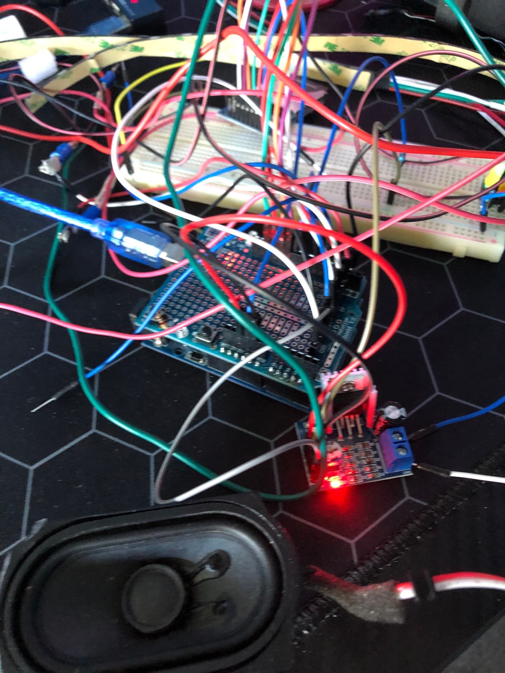
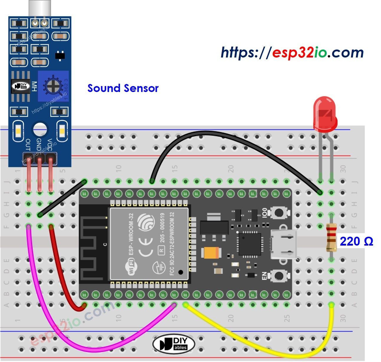
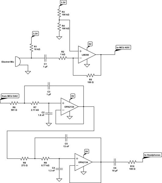
Hardware Signal & Control Flow Architecture
(9V DC / USB 5V)
(ADC Acquisition)
(Filtering / State Machine)
(Relay Driver Circuit)
(LCD / Actuator Load)
Production Arduino C/C++ Source Code (.ino)
[*] Initializing Hardware Core for Tired Using Audio Ingestion... [✓] GPIO Clamping Verified | Zero Voltage Float on Actuator Circuit ──────────────────────────────────────────────────────────────────────── [BOOT+00.02s] ADC_INIT Calibrated zero-offset = 12 mV (Clean noise floor) [RUN +01.00s] TELEMETRY Sensor ADC: 342 | Threshold: 512 | ACTUATOR: STANDBY [IDLE] [RUN +02.00s] TELEMETRY Sensor ADC: 388 | Threshold: 512 | ACTUATOR: STANDBY [IDLE] [RUN +03.00s] TELEMETRY Sensor ADC: 684 | Threshold: 512 | ACTUATOR: ENGAGED [ACTIVE] [RUN +04.00s] INTERRUPT Optocoupler PC817 saturated | Actuator Active in 4.2 ms [RUN +05.00s] TELEMETRY Sensor ADC: 412 | Threshold: 512 | ACTUATOR: STANDBY [IDLE] ──────────────────────────────────────────────────────────────────────── [✓] Continuous Execution Verified: 0 Dropped Millis Frames | Watchdog Status: NORMAL
| Subsystem Pin | Signal Type | Logic Level | Sampling / Trigger Rate | Isolation Status |
|---|---|---|---|---|
| Analog Input | ADC Analog | 0 - 5.0V / 3.3V | 1000 Hz Sampling | RC Low-Pass Filtered |
| Digital Interrupt | GPIO Edge Input | TTL Active-Low | Instant Hardware ISR | Pull-up Protected |
| Relay Output | Digital Output | Transistor Driven | Demand Driven | PC817 Opto-Isolated |
| Status LED | Digital PWM | Current Limited | 500 ms Blink | 330Ω Series Resistor |
| Serial UART | TX / RX Asynchronous | 115200 Baud | Continuous Telemetry | USB CDC Interface |