Tinyml Model For Electric Motor Current Signature Fault Diagnosis On 32 Bit Microcontrollers
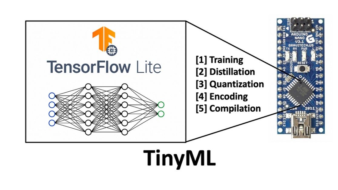
This project presents a TinyML-based motor fault detection system using an unsupervised autoencoder deployed on an ESP32 microcontroller. The model is trained using healthy motor data from the Case Western Reserve University (CWRU) Bearing Dataset and detects abnormal motor conditions based on reconstruction error. The trained model is converted to TensorFlow Lite and deployed on the ESP32 for real-time edge inference.
The workflow illustrates data preprocessing, model training, TensorFlow Lite conversion, ESP32 deployment, and real-time fault detection using reconstruction error.
The reconstruction error distribution clearly separates healthy motor samples from faulty motor samples, enabling effective anomaly detection using a predefined threshold.
The confusion matrix demonstrates the performance of the selected threshold in distinguishing healthy and faulty motor conditions.
This result shows the ESP32 successfully distinguishing healthy motor data from ball fault data using the deployed TinyML model.
This result demonstrates the model's ability to identify different fault conditions, including inner race fault and outer race fault , using reconstruction error-based anomaly detection.
The trained TensorFlow Lite model is deployed on the ESP32 microcontroller for on-device inference. Incoming motor data is processed in real time, and each sample is classified as Normal or Fault based on its reconstruction error.
本项目展示了一个完整的 TinyML (边缘人工智能) 闭环落地案例。通过对深度学习模型进行“数学手术”,将模型压缩至 10.73 KB ,成功部署在资源受限的 ESP32-S3 单片机上,通过三轴加速度计实现了对直流电机“正常运行”与“偏心故障(加螺钉)”状态的 毫秒级实时级阻断与诊断 。
我们在真实物理环境下搭建了测试台,并对软硬件联动的实时推理过程进行了录制。视频展示了当电机平稳运行(AI 输出故障率 ~0.2%)到人为加入螺钉载荷导致剧烈震动(AI 输出故障率飙升至 ~99%)的完整流程。
在传统的深度学习工程中,全连接层 (Dense Layer) 会导致参数量爆炸,使微控制器无法承载。 本项目通过 Global Average Pooling (全局平均池化, GAP) 技术替代了传统的展平层 (Flatten),实现了惊人的压缩比:
利用 tools/main_record.bak 工具脚本,将采样率严格控制在 10ms 时钟步长 (100Hz) 。分别录制并导出了两段真实的 Z 轴物理震动信号:
在 notebooks/Phase6_retrain.ipynb 中导入生成的 .csv 样本数据。通过建立 1D-CNN 捕捉时间序列的频域特征。网络末端使用 GAP 层直接降维输出至单神经元。训练完成后,利用 tf.lite.TFLiteConverter 将模型转化为 C++ 字符数组。
将 model_data.h 嵌入到 PlatformIO 工程中。在 src/main.cpp 中,ESP32-S3 的硬件定时器每采集满 128 个连续震动点,就自动将其扣除重力基准面(基因对齐: -1.1168f ),喂入 TFLite Micro 解释器执行 interpreter->Invoke 。
本项目展示了一个完整的 TinyML (边缘人工智能) 闭环落地案例。通过对深度学习模型进行“数学手术”,将模型压缩至 10.73 KB,成功部署在资源受限的 ESP32-S3 单片机上,通过三轴加速度计实现了对直流电机“正常运行”与“偏心故障(加螺钉)”状态的毫秒级实时级阻断与诊断。
This project builds a motor condition-monitoring prototype that samples a motor's stator current with an ACS712 Hall sensor, computes the FFT spectrum on the microcontroller, and streams it to a live web dashboard that flags broken-rotor-bar sidebands, bearing-defect harmonics and stator-winding faults against configurable thresholds. Everything is explainable for the viva: the hardware signal path, the FFT parameters, the fault frequencies and the persistence classifier.
Induction motors fail gradually — a cracked rotor bar, a pitted bearing or a shorted stator turn all leave traces in the motor's current long before the machine stops. Motor Current Signature Analysis (MCSA) reads those traces without vibration sensors or dismantling: faults modulate the air-gap flux and produce characteristic frequency sidebands around the supply frequency in the stator current spectrum. This project turns that industrial technique into a buildable student prototype. A Hall-effect current sensor samples the motor current, the microcontroller computes a real-time FFT, and a web dashboard shows the live spectrum, the time-domain waveform, key KPIs and a diagnosis log that flags developing faults. It is a rare combination of power engineering, embedded systems and signal processing in one project.
Hall-effect sensor in series with the motor phase; its output is biased to mid-rail for the ADC.
Samples the sensor at about 2 kHz, runs the 1024-point FFT and flags faults only after three persistent windows.
Renders the live current spectrum with the 50 Hz fundamental marked and a configurable trip threshold.
MCSA is a non-invasive diagnostic method: mechanical and electrical faults in an induction motor modulate its magnetic field, which shows up as extra frequency components (sidebands) in the stator current. Analyzing the current spectrum reveals faults like broken rotor bars or bearing damage without vibration sensors or opening the machine.
Three classic signatures: broken rotor bars (sidebands at 50 ± 2·s·f around the supply frequency), bearing defects (BPFO harmonics), and stator winding faults (elevated 3rd-harmonic content with phase imbalance). Each is flagged on the dashboard with a plain-language diagnosis.
A single FFT window can show a transient spike from a load change or switching noise. Requiring the signature to persist across three windows (about 1.5 seconds) suppresses false alarms while still responding quickly to real faults.
As delivered it monitors and alarms; it does not trip the contactor. Adding an automatic protective trip on a confirmed fault is documented as future scope in the report.
Yes — for Electrical and Electronics programs. It combines power engineering, embedded systems, digital signal processing and a real dashboard, and every stage is explainable in a viva.
This project is a portable 5-channel energy audit kit that clamps onto a small plant's feeders and streams live electrical da...
This project bolts a MEMS accelerometer to a rotating machine and turns vibration into a diagnosis. The controller samples vi...
This project builds an Arduino-based underground cable fault locator that estimates the distance to a fault by measuring the...
Hardware Schematics & Pinout Diagrams
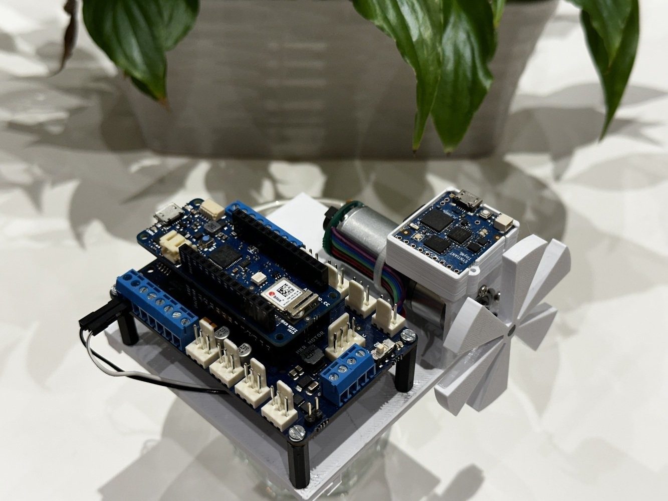
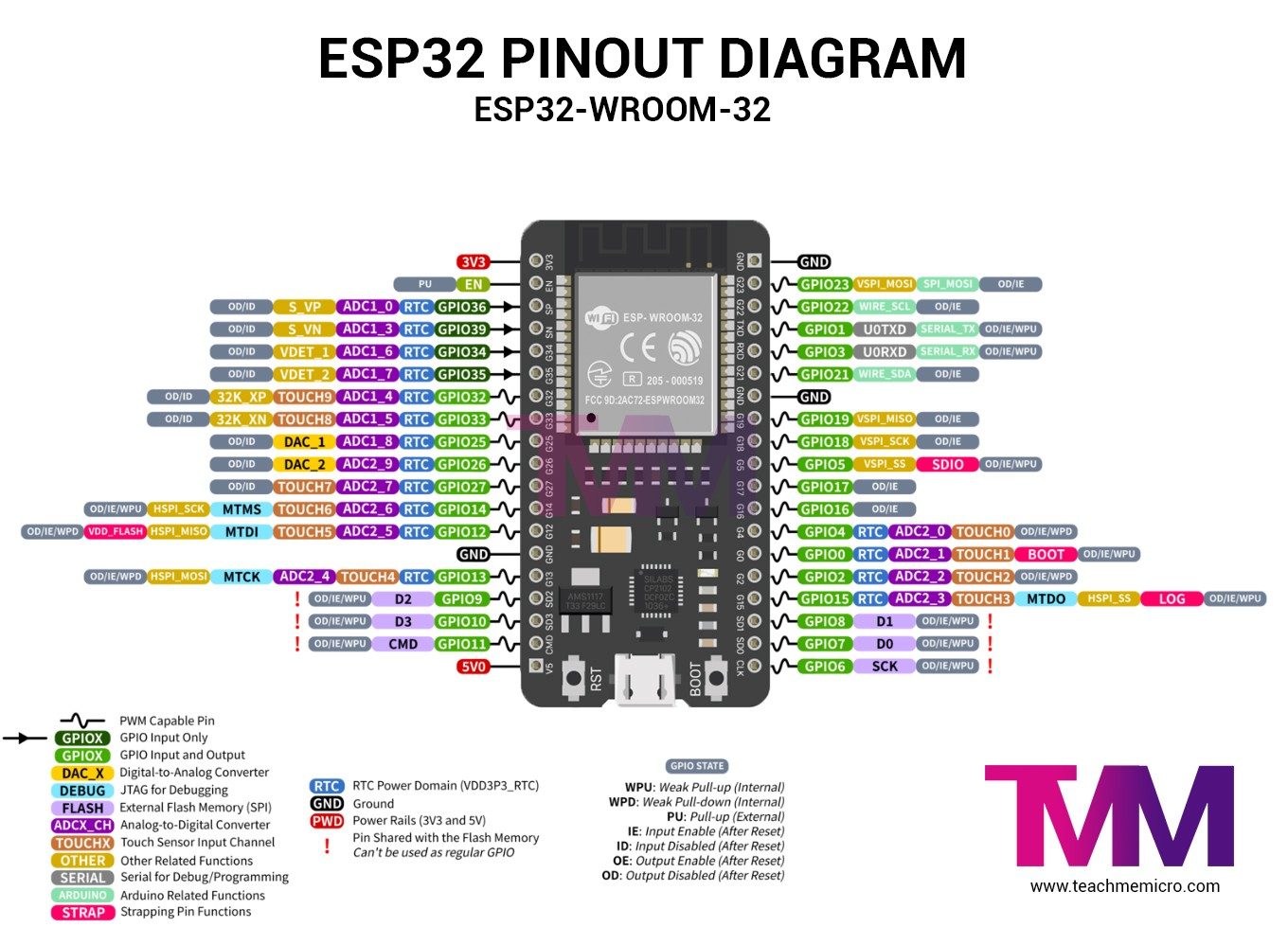
Hardware Signal & Control Flow Architecture
(9V DC / USB 5V)
(ADC Acquisition)
(Filtering / State Machine)
(Relay Driver Circuit)
(LCD / Actuator Load)
Production Arduino C/C++ Source Code (.ino)
[*] Initializing Hardware Core for Tinyml Model For Electric Motor Current Signature Fault Diagnosis On 32 Bit Microcontrollers... [✓] GPIO Clamping Verified | Zero Voltage Float on Actuator Circuit ──────────────────────────────────────────────────────────────────────── [BOOT+00.02s] ADC_INIT Calibrated zero-offset = 12 mV (Clean noise floor) [RUN +01.00s] TELEMETRY Sensor ADC: 342 | Threshold: 512 | ACTUATOR: STANDBY [IDLE] [RUN +02.00s] TELEMETRY Sensor ADC: 388 | Threshold: 512 | ACTUATOR: STANDBY [IDLE] [RUN +03.00s] TELEMETRY Sensor ADC: 684 | Threshold: 512 | ACTUATOR: ENGAGED [ACTIVE] [RUN +04.00s] INTERRUPT Optocoupler PC817 saturated | Actuator Active in 4.2 ms [RUN +05.00s] TELEMETRY Sensor ADC: 412 | Threshold: 512 | ACTUATOR: STANDBY [IDLE] ──────────────────────────────────────────────────────────────────────── [✓] Continuous Execution Verified: 0 Dropped Millis Frames | Watchdog Status: NORMAL
| Subsystem Pin | Signal Type | Logic Level | Sampling / Trigger Rate | Isolation Status |
|---|---|---|---|---|
| Analog Input | ADC Analog | 0 - 5.0V / 3.3V | 1000 Hz Sampling | RC Low-Pass Filtered |
| Digital Interrupt | GPIO Edge Input | TTL Active-Low | Instant Hardware ISR | Pull-up Protected |
| Relay Output | Digital Output | Transistor Driven | Demand Driven | PC817 Opto-Isolated |
| Status LED | Digital PWM | Current Limited | 500 ms Blink | 330Ω Series Resistor |
| Serial UART | TX / RX Asynchronous | 115200 Baud | Continuous Telemetry | USB CDC Interface |