Smart Substation Battery Bank Health Analyzer Measuring Internal Resistance Via AC Injection
This project is an Arduino-based battery analyzer designed for measuring battery capacity and estimating internal resistance + constant current. It can be used not only for single-cell 18650 Li-ion batteries, but also for other rechargeable batteries and battery packs up to approximately 20 V, depending on the voltage divider, load resistor, MOSFET, cooling, and calibration settings.
The project uses a 20x4 character LCD screen for menu navigation, capacity measurement, constant current load testing, internal resistance measurement, and device settings.
This mode is used to discharge the connected battery with a selected current and calculate the measured capacity.
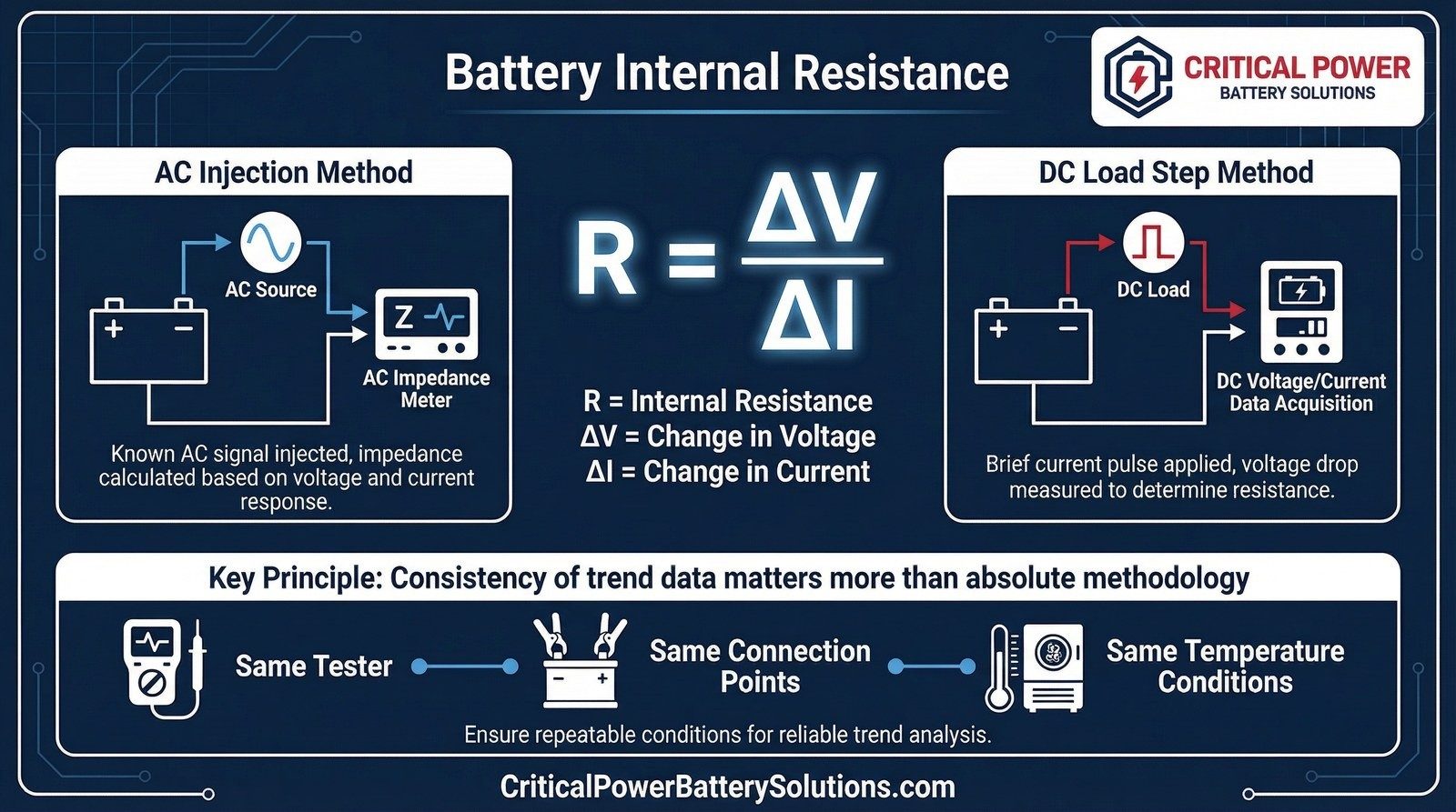
This mode estimates the internal resistance of the battery by comparing voltage values under different load current conditions.
The settings menu includes options such as sound, ADC offset compensation, and saving calibration values to EEPROM.
The schematic below shows the Arduino Nano connections, LCD interface, voltage divider, MOSFET load stage, current sensing section, buzzer, fan output, and power supply regulators.
The PCB layout includes the Arduino Nano, LCD connector, MOSFET load section, resistor load bank, voltage measurement input, current sense path, fan output, and power supply section.
This project is for educational and testing purposes only. When working with Li-ion batteries, lead-acid batteries, NiMH packs, or other rechargeable batteries, caution must be exercised against short circuits, overcurrent, reverse polarity, overheating, and incorrect voltage divider calibration.
For battery voltages higher than a single Li-ion cell, the voltage divider, load resistor power rating, MOSFET voltage/current rating, heat dissipation, and firmware calibration values must be checked and adjusted before use.
The maximum usable battery voltage depends on the voltage divider ratio, ADC input limits, MOSFET rating, load resistor power rating, fuse rating, PCB trace current capacity, and cooling performance.
This Arduino Nano version is based on / adapted from the original rechargeable battery analyzer project.
Arduino Nano Battery and Accumulator Capacity and Internal Resistance Tester. This is a project I started at the request of one of our readers. I also work with Li-ion cells from time to time and I enjoy related projects. I progressed from internal resistance measurement of cells to this project.
The implemented Arduino project is a battery analyzer device that can perform capacity, Wh, internal resistance, and constant-current load tests on different battery types, from 18650 Li-ion cells to small lead-acid batteries.
The basic idea of the circuit was taken from an older ATmega328P -based battery analyzer project. The source code was adapted so it could be used with Arduino Nano, and some improvements were made according to the problems encountered during workshop tests.
The aim of the project is not only to discharge a battery and see the mAh value. It also allows you to observe how much the battery voltage sags under load, approximately what level its internal resistance is, how the cell, battery, or power supply behaves in constant-current load mode, and how the Wh value is formed at the end of the test.
I prepared this application especially for single-cell 18650 Li-ion cells. However, the original operating range of the circuit is approximately between 0.8 V and 20 V. You can modify the code according to your needs; how to do this is also explained in the article.
For this reason, if a suitable termination voltage and current value are selected, it can also be used with different types of cells and batteries.
For basic information about 18650 cells, you can also refer to a previously published article explaining what a 18650 cell is.
The original software was written in AVR C by @F. Stefanec . Source page: tefatronix.g6.cz/display.php?page=batmeter
Code::Blocks was used as the development environment, AVR-GCC as the compiler, and avrdude with USBasp on the programming side.
Since the original circuit also uses an ATmega328P, adapting it to the Arduino Nano worked well. This is because the Arduino Nano uses the same microcontroller family.
On the code side, the process was not to rewrite the project from scratch using Arduino libraries, but to preserve the logic of the original AVR C code and make it compilable under the Arduino IDE and uploadable through the Arduino Nano bootloader.
The circuit consists of two main sections: the control section and the load section. The control section includes the Arduino Nano, LCD, buttons, buzzer, fan output, LM35, voltage measurement input, and adjustment components. The load section consists of the PWM filter, LM358 op-amp, IRFP260 MOSFET, shunt resistors, and battery connection.
The Arduino Nano generates a signal from the PWM output. This PWM signal is converted by an RC filter into a voltage close to an analog level.
The op-amp compares this reference voltage with the voltage across the shunt resistors.
The MOSFET gate is driven until the voltage across the shunt resistor reaches the target level. In this way, the circuit tries to draw a constant current from the battery.
This structure is a classic linear electronic load topology. The MOSFET does not operate as a switching element; it operates in the linear region and converts the excess energy into heat.
Therefore, in long-duration and high-current tests, using a large heatsink and a fan for the MOSFET is mandatory.
The Arduino Nano manages the entire menu structure of the device, LCD text, button readings, ADC measurements, EEPROM records, PWM control, and test durations.
While the original circuit used the ATmega328P directly, this adaptation uses the same processor on the Arduino Nano board.
A 20×4 character LCD is used in the project. The LCD displays the main menu, capacity test, constant-current load mode, internal resistance measurement, and settings.
Using a 20×4 display provides a major advantage, because voltage, current, time, mAh, mWh, and test status can be seen at the same time.
In the load section, a powerful N-channel IRFP260 MOSFET is operated in the linear region. The important point here is that the MOSFET does not only work like a switch that turns the current on and off. A significant amount of power is dissipated on the MOSFET.
For example, when a fully charged 4.2V 18650 cell is tested at 1A, approximately 4W of power is dissipated on the load side.
However, in a high-level test such as 20V at 2.5A, this power can approach 50W. For this reason, thermal design is as important as the software in this circuit.
In this circuit, the MOSFET works as the constant-current electronic load element. In other words, the MOSFET does not operate fully on or fully off like a switching element; it operates in the linear region and allows the desired current to be drawn from the battery.
Therefore, when choosing the MOSFET, attention should be paid not only to the current rating, but also to cooling, package type, and the power that will be dissipated on it.
If currents such as 1A or 1.5A are used in single-cell 18650 tests, the power on the MOSFET is usually at the level of a few watts.
For example, with a fully charged 18650 cell at 4.2V and a 1.5A test current, approximately 6W of power may be generated on the MOSFET. In this case, a well-cooled TO-220 MOSFET is sufficient for most applications.
However, if the device will be used for 12V batteries, higher-voltage battery packs, or long-duration load tests above 2A, a larger-package and more powerful MOSFET such as the IRFP260N should be preferred.
If only 18650 cell testing will be performed, using an IRFP260N is not mandatory. TO-220 package MOSFETs such as IRFZ44N, IRF540N, or IRF3205 may be sufficient at 1A – 1.5A levels.
However, the MOSFET must be mounted on a heatsink. Since the circuit operates as a linear electronic load, the heat generated on the MOSFET is directly related to the test current and battery voltage.
Large-package MOSFETs such as the IRFP260N should mainly be preferred when the device is intended to remain general-purpose, when 12V battery tests will be performed, or when long-duration operation at higher currents is required.
Shunt resistors are used on the MOSFET source side for current measurement and regulation.
Three 0.33 ohm resistors are connected in parallel. In this case, the equivalent resistance is approximately 0.11 ohm.
In the original application, the shunt resistors were 1W; I used 2W for better reliability. If you will work with higher voltages and currents, 2W is suitable, and even 3W can be used.
This table can also be used for calibration. When 1 A is selected in constant-current mode, approximately 110 mV should be seen across the shunt terminals.
If this value is very different, the current setting, shunt resistor value, op-amp section, or PWM filter side should be checked.
The original circuit uses an LM358. Since the LM358 can operate from a single supply, is easy to find, and is inexpensive, it is frequently used in this type of circuit.
However, in this project, because the op-amp compares small shunt voltages, offset error directly turns into current error.
The author also mentions this on his page and recommends a quality op-amp for better measurement.
If your goal is only to separate good and bad batteries and you do not need very precise measurements, the LM358 will do the job.
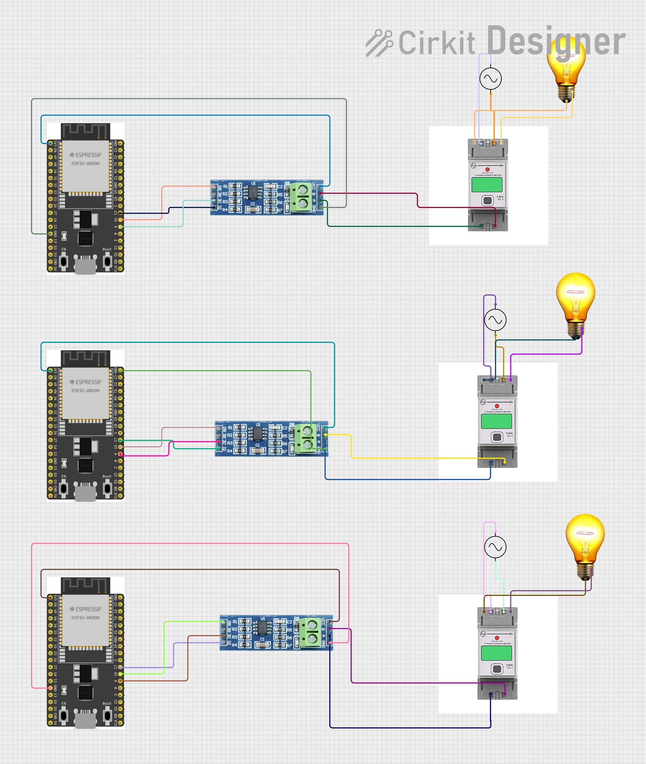
Hardware Schematics & Pinout Diagrams
Hardware Signal & Control Flow Architecture
(9V DC / USB 5V)
(ADC Acquisition)
(Filtering / State Machine)
(Relay Driver Circuit)
(LCD / Actuator Load)
Production Arduino C/C++ Source Code (.ino)
[*] Initializing Hardware Core for Smart Substation Battery Bank Health Analyzer Measuring Internal Resistance Via AC Injection... [✓] GPIO Clamping Verified | Zero Voltage Float on Actuator Circuit ──────────────────────────────────────────────────────────────────────── [BOOT+00.02s] ADC_INIT Calibrated zero-offset = 12 mV (Clean noise floor) [RUN +01.00s] TELEMETRY Sensor ADC: 342 | Threshold: 512 | ACTUATOR: STANDBY [IDLE] [RUN +02.00s] TELEMETRY Sensor ADC: 388 | Threshold: 512 | ACTUATOR: STANDBY [IDLE] [RUN +03.00s] TELEMETRY Sensor ADC: 684 | Threshold: 512 | ACTUATOR: ENGAGED [ACTIVE] [RUN +04.00s] INTERRUPT Optocoupler PC817 saturated | Actuator Active in 4.2 ms [RUN +05.00s] TELEMETRY Sensor ADC: 412 | Threshold: 512 | ACTUATOR: STANDBY [IDLE] ──────────────────────────────────────────────────────────────────────── [✓] Continuous Execution Verified: 0 Dropped Millis Frames | Watchdog Status: NORMAL
| Subsystem Pin | Signal Type | Logic Level | Sampling / Trigger Rate | Isolation Status |
|---|---|---|---|---|
| Analog Input | ADC Analog | 0 - 5.0V / 3.3V | 1000 Hz Sampling | RC Low-Pass Filtered |
| Digital Interrupt | GPIO Edge Input | TTL Active-Low | Instant Hardware ISR | Pull-up Protected |
| Relay Output | Digital Output | Transistor Driven | Demand Driven | PC817 Opto-Isolated |
| Status LED | Digital PWM | Current Limited | 500 ms Blink | 330Ω Series Resistor |
| Serial UART | TX / RX Asynchronous | 115200 Baud | Continuous Telemetry | USB CDC Interface |