Smart Residential Energy Meter With Automated Dynamic Load Shedding And GSM Billing Interface
Automated energy monitoring, billing and payment notification system using GSM communication.
The GSM Based Smart Energy Meter is an embedded IoT-oriented system designed to automate electricity monitoring and billing.
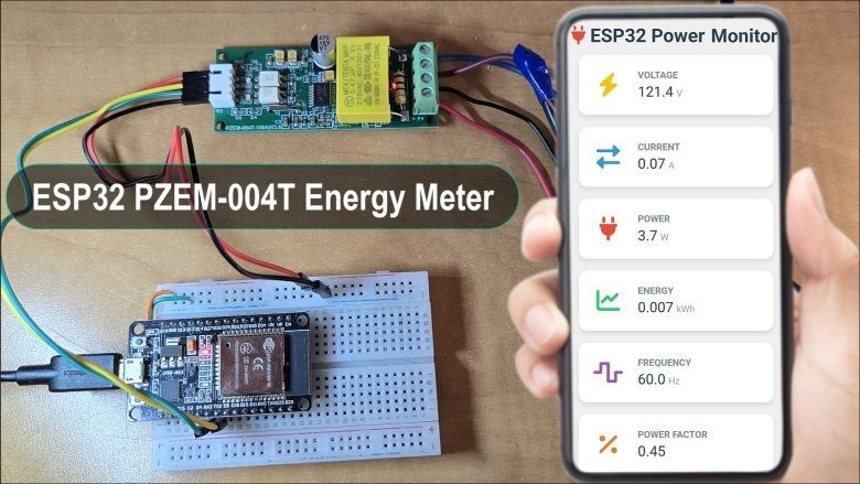
The system measures electrical parameters such as voltage, current, power and energy consumption using the PZEM-004T energy monitoring module connected to an Arduino Uno .
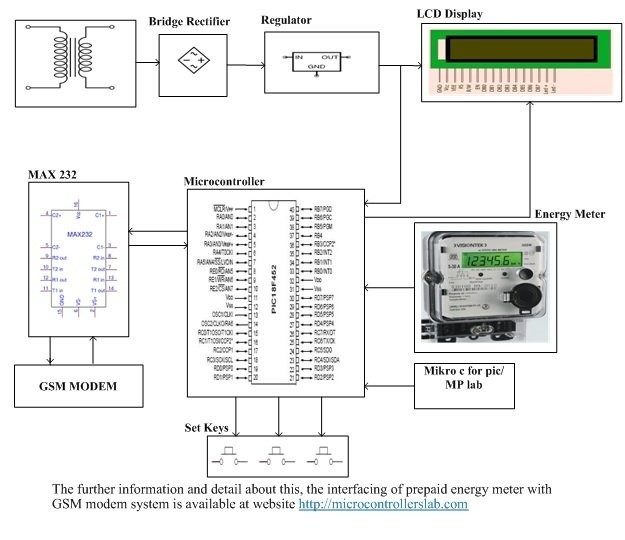
The measured data is displayed on a 16×4 I2C LCD , while a GSM SIM800C module is used to send billing information and notifications through SMS.
The project also includes a Node.js backend integrated with the Razorpay payment gateway to generate online payment links for electricity bills.
Measure → Process → Display → Generate Bill → Send SMS → Online Payment → Load Control
The measured values are displayed on the 16×4 I2C LCD , allowing the user to monitor the system locally.
The system calculates the electricity bill based on the measured energy consumption and the configured tariff.
For project demonstration purposes, the billing cycle can be simulated to represent a longer period within a shorter real-time duration.
The SIM800C GSM module sends SMS notifications containing billing and usage information to the registered user.
The Arduino-side system communicates with the backend, where the Node.js server handles bill-related processing and Razorpay integration.
A 5V relay module is used to control the connected load based on the system's payment/load-control logic.
The project uses a Node.js backend to handle the server-side billing and payment workflow.
Configure the required Razorpay credentials and other project-specific settings before running the payment functionality.
The prototype was tested using an AC load and demonstrated the complete monitoring-to-billing workflow.
Bhavya A R Assistant Professor Department of Electronics and Telecommunication Engineering Bangalore Institute of Technology
Bangalore Institute of Technology Department of Electronics and Telecommunication Engineering VTU Belagavi
⚡ GSM Based Smart Energy Meter Automated Energy Monitoring • Billing • GSM Notification • Online Payment
GSM-based smart energy meter with real-time monitoring, automated billing, and Razorpay payment integration using Arduino and Node.js
This project presents the design and implementation of an IoT-enabled Smart Energy Meter using Arduino Mega 2560 and GSM module for remote energy monitoring, real-time data transmission, and automated billing.
📍 Developed as part of the final year B.Tech (Electrical Engineering) project at Sardar Patel College of Engineering , Mumbai.
With rising energy demands and distribution losses, utility companies need modern metering systems that are efficient, accurate, and remotely manageable. This project aims to:
In this project, we will make a GSM Based Prepaid Electricity Energy Meter using Arduino. Prepaid Electricity Energy Meter is one of the best concepts for the current electricity payment system. In this system, you can recharge the device and update the balance as we do on our mobile phones.
By sending a simple SMS, you can recharge the electricity balance through this system. It can also disconnect the home power supply connection if there is a low or zero balance in the system. And this system will read the energy meter readings and automatically send some updates to the user’s mobile phone like low balance alert, cut off alert, resume alert and recharge alert. The Anti-Theft Alert can also be detected when someone tries stealing the meter by opening the lid. So, let us see how we can build this project.
There is an advance version of this project based on Internet of Thing, which you may look into: 1. IoT AC Energy Meter using Old Blynk 2. IoT AC Energy Meter using New Blynk 3. IoT DC Energy Meter
Following is the list of materials that you need to make an Arduino & GSM Based Prepaid Energy Meter. You can purchase all the components from the following link.
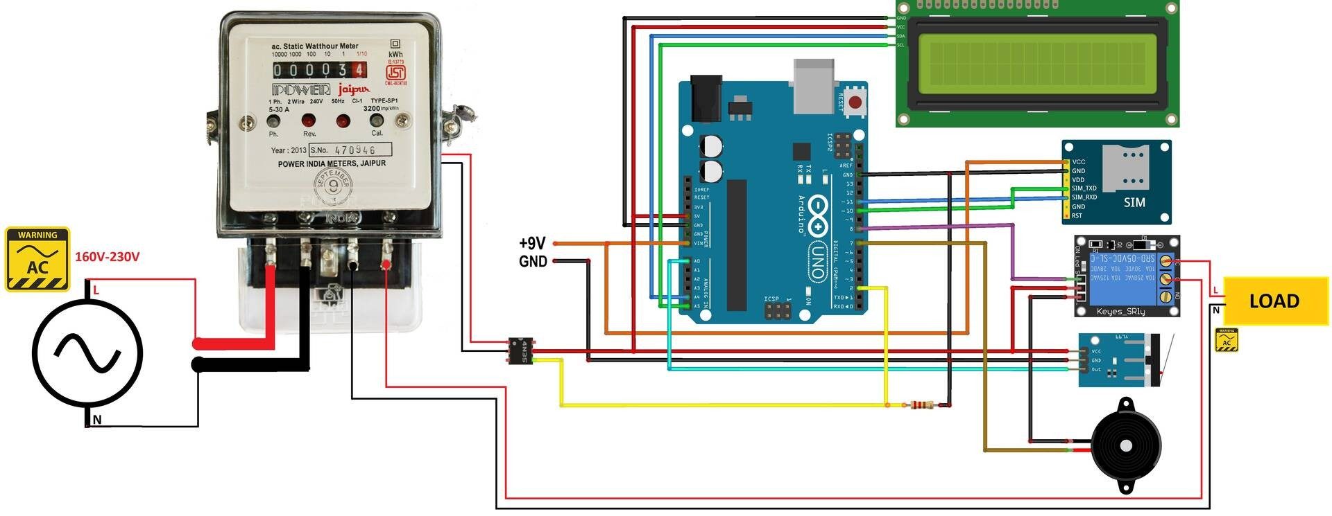
The circuit diagram for GSM Based Prepaid Energy Meter is very simple. The Analog Electricity Energy Meter input terminal connects to 220V AC Power Supply. Its output terminal connects to the output of the single-channel Relay Module. All the loads for electricity also connect to the Relay as shown in the circuit.
The 16×2 I2C LCD Display connects to the I2C Pins of the Arduino UNO Board. We have used SIM800 GSM Module for GMS SMS functions which is the most important part of this project. The GSM has UART Pin as Tx & Rx which connects via Software Serial to digital pins 11 and 12 of Arduino. The GSM Module requires 9V Power Supply. So an external 9V DC power supply like DC Power Adapter can be used. Hence the GSM and Arduino both are powered via 9V DC Adapter.
The Relay, Buzzer, and Limit Switch are connected to D8, D7 & A0 of Arduino. Remember to take precautions as this circuit is dangerous due to AC Mains.
As shown here, you can assemble the circuit in a combined board. The top of the board has only the analog meter and LCD Display. Inside the box, the Arduino Board, GSM Module, Relay, and 4N35 Optocoupler IC are placed together. The Limit switch is placed at the opening of the meter door. It is used to check whether the box is opened or not and can prevent theft.
In this project, you can connect anything to the load such as Fan, Bulb, Heater, and everything that you use at home. To test this system you can connect the whole device directly to the 220V AC power supply.
The most important thing is how do you connect the meter to the Arduino. For this open the meter first. At the back of the meter, there is a Pulse LED or Cal LED terminals which are basically cathode and Anode.
You need to solder two wires to these terminals. After these, connect the anode & cathode terminal of the LED at pin number 1 and pin number 2 of the optocoupler. Now, this optocoupler is connected to digital pin D2 of Arduino.
I used EasyEDA to design the PCB & Schematic. The Schematic & PCB Board for Prepaid Energy Meter looks something like the below.
The complete program for GSM Based Prepaid Energy Meter using Arduino is given below. The code is mostly formatted for GSM AT Commands to recharge and test the system along with output feedback messages.
You need to make changes to the above lines in this code. Replace the mobile number in the following lines of the code with the number you want the SMS to send.
When you power on the device, the LCD will display the unit, pulse, and price as zero.
Now we need to send an SMS to operate this device. Before that, we need to recharge this meter as there is no money to operate this device. You can recharge 100, 200, 300 & 400 at a single time. With the recharged money the electricity load will always be active as long as the amount doesn’t reach to zero.
To recharge with 100 balance, type ATrech1 & send. Here 1 means 100. If you want to recharge it with 200 simply replace 1 with 2. You will get a feedback message as an SMS that says “recharge is done”. The LCD will also display the same. Immediately the load will turn on.
As long as the pulse LED blinks, the counting goes on and the pulse count is displayed on LCD Screen. Also, there is a deduction in the recharged amount. We also set the limit to 60. As the amount goes to 60, the GSM will send an SMS saying the balance is low and you need to recharge it again. So basically, it’s an indication as well as a warning.
When the power consumption increases and the price goes further down till the amount reaches zero. In this instance, the load will turn off and there is an electricity cut-off. You will receive an SMS saying the balance is finished and you need to recharge it again.
This process continues even after there is a power cut. This is because the last pulse count and price value are stored in the EEPROM of the microcontroller.
Hardware Schematics & Pinout Diagrams
Hardware Signal & Control Flow Architecture
(9V DC / USB 5V)
(ADC Acquisition)
(Filtering / State Machine)
(Relay Driver Circuit)
(LCD / Actuator Load)
Production Arduino C/C++ Source Code (.ino)
[*] Initializing Hardware Core for Smart Residential Energy Meter With Automated Dynamic Load Shedding And GSM Billing Interface... [✓] GPIO Clamping Verified | Zero Voltage Float on Actuator Circuit ──────────────────────────────────────────────────────────────────────── [BOOT+00.02s] ADC_INIT Calibrated zero-offset = 12 mV (Clean noise floor) [RUN +01.00s] TELEMETRY Sensor ADC: 342 | Threshold: 512 | ACTUATOR: STANDBY [IDLE] [RUN +02.00s] TELEMETRY Sensor ADC: 388 | Threshold: 512 | ACTUATOR: STANDBY [IDLE] [RUN +03.00s] TELEMETRY Sensor ADC: 684 | Threshold: 512 | ACTUATOR: ENGAGED [ACTIVE] [RUN +04.00s] INTERRUPT Optocoupler PC817 saturated | Actuator Active in 4.2 ms [RUN +05.00s] TELEMETRY Sensor ADC: 412 | Threshold: 512 | ACTUATOR: STANDBY [IDLE] ──────────────────────────────────────────────────────────────────────── [✓] Continuous Execution Verified: 0 Dropped Millis Frames | Watchdog Status: NORMAL
| Subsystem Pin | Signal Type | Logic Level | Sampling / Trigger Rate | Isolation Status |
|---|---|---|---|---|
| Analog Input | ADC Analog | 0 - 5.0V / 3.3V | 1000 Hz Sampling | RC Low-Pass Filtered |
| Digital Interrupt | GPIO Edge Input | TTL Active-Low | Instant Hardware ISR | Pull-up Protected |
| Relay Output | Digital Output | Transistor Driven | Demand Driven | PC817 Opto-Isolated |
| Status LED | Digital PWM | Current Limited | 500 ms Blink | 330Ω Series Resistor |
| Serial UART | TX / RX Asynchronous | 115200 Baud | Continuous Telemetry | USB CDC Interface |