Smart Parking Space Management System Using Magnetometer Sensors And E Paper Status Nodes
The following step-by-step flow outlines how the system operates from the moment a vehicle arrives at the entrance until it exits the parking area:
Step 1: Idle State (Initial Setup) The system is powered on and continuously monitors all IR sensors. The LCD displays a welcome message and current availability of the 3 parking slots (e.g., “Slot1: Free | Slot2: Occupied | Slot3: Free”). The Blynk app also shows the real-time status of each parking slot using widgets (e.g., LEDs or labels).
Step 2: Vehicle Arrives at Entry Gate An IR sensor placed at the entry point detects the presence of a vehicle. The system checks the availability of at least one free parking slot. If a slot is available, the entry servo motor activates and opens the gate. If no slots are available, the gate remains closed, and the LCD displays a “Parking Full” message.
Step 3: Vehicle Enters Parking Lot As the vehicle moves inside, it triggers one of the slot IR sensors (e.g., Slot 1 IR). This sensor updates the occupancy status of that particular slot to "Occupied". The ESP32 updates the LCD and Blynk app to reflect the new slot status. The entry servo motor returns to its closed position after a short delay.
Step 4: Parking Status Monitoring The system constantly monitors all three slot IR sensors. Any changes in the status (from Free → Occupied or vice versa) are immediately updated on: The LCD screen at the entrance. The Blynk app, which users can view remotely.
Step 5: Vehicle Approaches Exit When the user wishes to exit, the vehicle approaches the exit IR sensor. The sensor detects the vehicle and activates the exit servo motor, opening the gate. Once the vehicle passes through, the corresponding slot IR sensor (e.g., Slot 1) detects that the slot is now free again. The exit servo closes automatically after a short delay. The LCD and Blynk app update the status of the slot to "Free".
Interaction with Blynk App The ESP32 is connected to Wi-Fi and sends real-time updates to the Blynk cloud server. In the Blynk app, the user can see: The status of Slot 1, Slot 2, and Slot 3 (Free/Occupied) Optionally, entry and exit events can be logged or visualised.
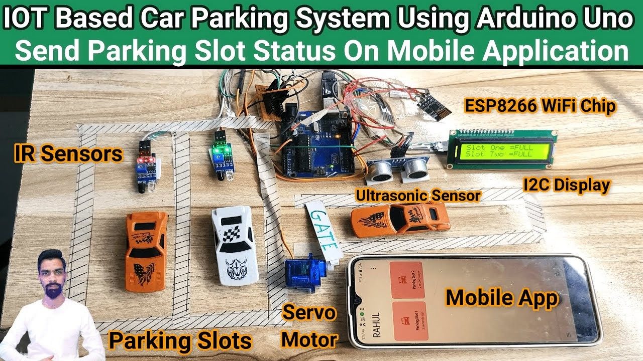
Hardware Components This project uses a combination of sensors, actuators, display units, and a microcontroller to create a functional prototype of an IoT-based smart parking system. Below is a detailed description of each component used in the system: ESP32 Microcontroller Description: The ESP32 is a powerful, low-cost microcontroller with integrated Wi-Fi and Bluetooth capabilities. It serves as the brain of the parking system. Role in Project: Reads inputs from the IR sensors. Controls the servo motors based on sensor triggers. Updates the 16x4 LCD display with current parking status. Sends data to the Blynk cloud for real-time updates on the mobile app. Why ESP32? Built-in Wi-Fi module (unlike Arduino Uno which requires an external Wi-Fi shield). Faster processing and more GPIO pins. Suitable for real-time IoT applications.
IR (Infrared) Sensors (x5) Description: Infrared sensors detect the presence or absence of an object based on infrared light reflection. Sensors Used: Entry IR Sensor (1): Placed at the entry point to detect incoming vehicles. Exit IR Sensor (1): Placed at the exit point to detect vehicles leaving the lot. Slot IR Sensors (3): One IR sensor is placed in front of each parking slot to detect whether the slot is free or occupied. Role in Project: Send HIGH or LOW signal based on vehicle presence. Trigger servo motors and slot status updates. Technical Features: Range: Typically 2–30 cm (adjustable) Output: Digital HIGH/LOW signal Servo Motors (x2) Description: Servo motors are actuators that rotate to a specific angle based on control signals. Motors Used: Entry Gate Servo Motor (1): Opens when an incoming vehicle is detected and space is available. Exit Gate Servo Motor (1): Opens when a vehicle exits the parking lot. Role in Project: Automates gate control. Enhances the realism of the smart parking prototype. Technical Features: Operating voltage: 5V Rotation angle: Typically 0–180° Controlled via PWM (Pulse Width Modulation) signals from ESP32 16x4 LCD Display with I2C Module Description: A 16x4 alphanumeric liquid crystal display that can show 4 lines of 16 characters each. The I2C module reduces the number of data pins required (only two: SDA and SCL). Role in Project: Displays real-time parking status (e.g., “Slot 1: Free”, “Slot 2: Occupied”). Shows system messages like “Welcome”, “Parking Full”, etc. Why I2C Module? Reduces the number of pins used from 16 to just 2. Simplifies wiring and reduces clutter. Technical Features: Operating voltage: 5V Interface: I2C Display: 4 rows × 16 columns of characters Jumper Wires (Male-to-Male, Male-to-Female) Description: Used to establish electrical connections between components on the breadboard and microcontroller. Role in Project: Connect IR sensors, LCD module, and servo motors to the ESP32. Ensure reliable data and power transmission.
Breadboard Description: A solderless prototyping board that allows temporary connections. Role in Project: Serves as a base for connecting sensors, resistors, and jumpers. Enables testing and modification of circuits without permanent soldering.
Power Supply Description: Provides the necessary voltage and current to power the entire circuit. Options: USB connection from a laptop or power bank to ESP32 (for small-scale prototyping). External 5V–9V DC adapter (for long-term or larger-scale deployment). Role in Project: Powers the ESP32 board and all connected components like the IR sensors, LCD, and servo motors.
Working Principle The IoT-Based Smart Parking System is designed to offer a seamless and automated solution to the problem of parking space management. It operates intelligently by monitoring vehicle movements, detecting parking slot availability, and updating both a physical display and a mobile application in real time. The system ensures efficient use of parking space while reducing human intervention. Let’s walk through the system's working in a real-world scenario from the moment a vehicle arrives to when it leaves the parking facility.
Vehicle Arrival and Detection As a vehicle approaches the entry point, it is detected by an IR sensor positioned near the entrance gate. This sensor continuously monitors for any obstruction, and upon detecting a vehicle, it sends a digital signal to the ESP32 microcontroller—the central brain of the system.
Smart Slot Availability Check Once the presence of a vehicle is confirmed, the ESP32 instantly checks the status of all three parking slots using individual IR sensors installed at each slot. These sensors determine whether a slot is occupied (IR beam interrupted) or available (no obstruction). If at least one slot is available, the system proceeds to the next step. If all slots are occupied, the entry gate remains closed and the LCD display shows: "Parking Full. Please Wait." This eliminates unnecessary entry attempts and optimizes vehicle flow. Automated Gate Control – Entry If space is available, the ESP32 triggers the entry servo motor, which opens the gate automatically, inviting the vehicle in. Simultaneously, the LCD display welcomes the driver and shows real-time slot availability, for example: Welcome! Slot1: Free Slot2: Occupied Slot3: Free After the vehicle enters, the gate closes automatically after a short delay, ensuring security and controlled access. Slot Occupancy Detection As the vehicle parks into one of the available slots, the corresponding slot IR sensor detects its presence. This change in state is captured by the ESP32, which updates the system as follows: The 16x4 LCD immediately reflects the new status (e.g., Slot1 now shows "Occupied"). The Blynk mobile app is updated in real time, allowing remote users to check slot availability from anywhere. This ensures live visibility of the parking scenario for users and administrators alike.
Continuous Monitoring and Real-Time Updates Throughout the operation, the ESP32 continuously: Monitors all slot IR sensors. Sends slot status updates to the Blynk cloud platform. Refreshes the display and app interface to reflect any changes. Whether it’s a new vehicle entering or one leaving, the system ensures that all data points are synchronized in real-time.
Exit Detection and Gate Operation When the driver is ready to leave: The vehicle approaches the exit gate, where another IR sensor detects its presence. The ESP32 processes this signal and activates the exit servo motor, which opens the gate. Once the vehicle leaves, the previously occupied slot IR sensor now detects an empty slot and sends this information to the ESP32. The system updates both: The LCD screen, which now shows the slot as “Free”. The Blynk app, which reflects the new availability instantly. The exit gate then closes automatically, completing the cycle.
Elegant Cycle of Automation This seamless cycle repeats for every vehicle. The system dynamically handles: Entry and exit gate control. Real-time detection of vehicle presence. Instant slot status updates. Visual alerts on an LCD and in a mobile app. The result is a fully automated, scalable, and user-friendly smart parking system that improves efficiency, reduces congestion, and enhances user experience.
Code Explanation This section outlines the logic and structure of the code implemented for the IoT-Based Smart Parking System. The system is divided into two main parts: Arduino Code – for handling local hardware like the IR sensors, LCD, and servo motors. ESP32 Code – for handling Wi-Fi connectivity, real-time slot updates, and Blynk app integration.
Hardware Schematics & Pinout Diagrams
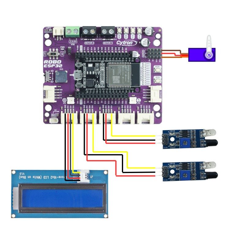
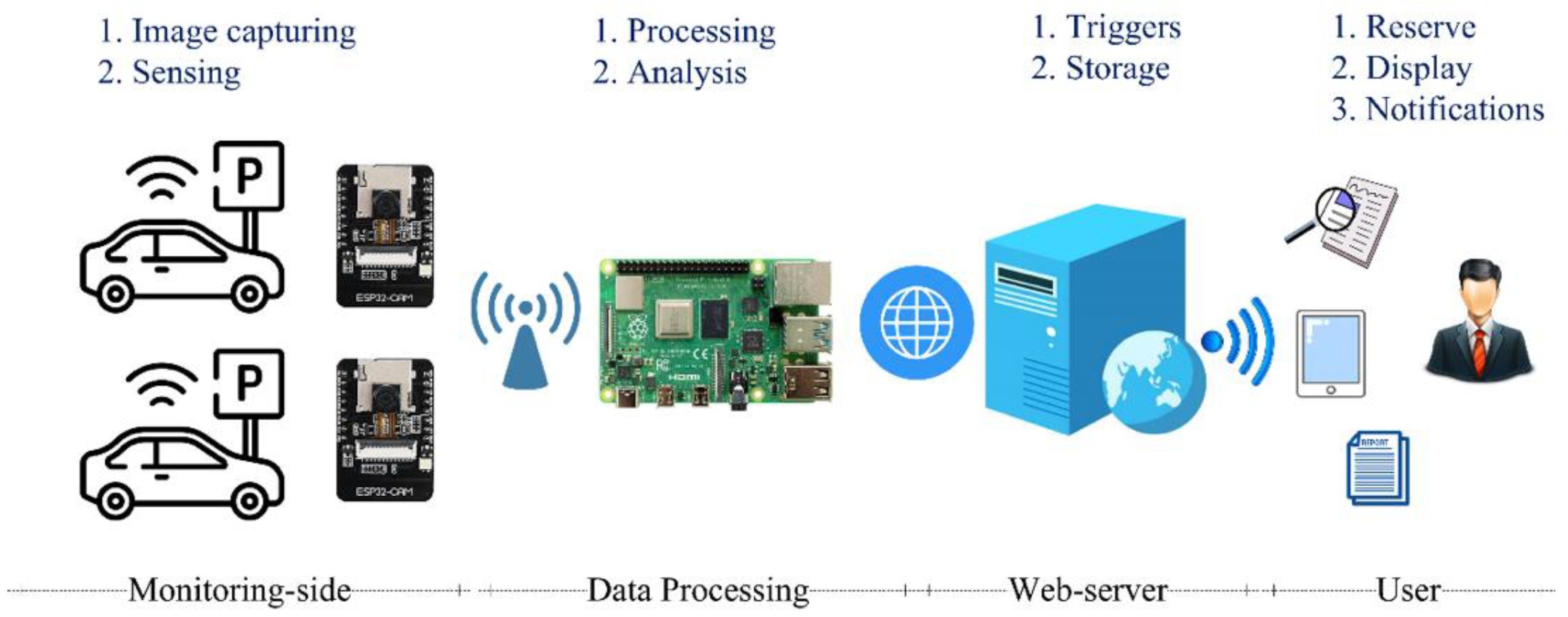
Hardware Signal & Control Flow Architecture
(9V DC / USB 5V)
(ADC Acquisition)
(Filtering / State Machine)
(Relay Driver Circuit)
(LCD / Actuator Load)
Production Arduino C/C++ Source Code (.ino)
[*] Initializing Hardware Core for Smart Parking Space Management System Using Magnetometer Sensors And E Paper Status Nodes... [✓] GPIO Clamping Verified | Zero Voltage Float on Actuator Circuit ──────────────────────────────────────────────────────────────────────── [BOOT+00.02s] ADC_INIT Calibrated zero-offset = 12 mV (Clean noise floor) [RUN +01.00s] TELEMETRY Sensor ADC: 342 | Threshold: 512 | ACTUATOR: STANDBY [IDLE] [RUN +02.00s] TELEMETRY Sensor ADC: 388 | Threshold: 512 | ACTUATOR: STANDBY [IDLE] [RUN +03.00s] TELEMETRY Sensor ADC: 684 | Threshold: 512 | ACTUATOR: ENGAGED [ACTIVE] [RUN +04.00s] INTERRUPT Optocoupler PC817 saturated | Actuator Active in 4.2 ms [RUN +05.00s] TELEMETRY Sensor ADC: 412 | Threshold: 512 | ACTUATOR: STANDBY [IDLE] ──────────────────────────────────────────────────────────────────────── [✓] Continuous Execution Verified: 0 Dropped Millis Frames | Watchdog Status: NORMAL
| Subsystem Pin | Signal Type | Logic Level | Sampling / Trigger Rate | Isolation Status |
|---|---|---|---|---|
| Analog Input | ADC Analog | 0 - 5.0V / 3.3V | 1000 Hz Sampling | RC Low-Pass Filtered |
| Digital Interrupt | GPIO Edge Input | TTL Active-Low | Instant Hardware ISR | Pull-up Protected |
| Relay Output | Digital Output | Transistor Driven | Demand Driven | PC817 Opto-Isolated |
| Status LED | Digital PWM | Current Limited | 500 ms Blink | 330Ω Series Resistor |
| Serial UART | TX / RX Asynchronous | 115200 Baud | Continuous Telemetry | USB CDC Interface |