Smart Orthopedic Cast With Integrated Pressure And Moisture Compartment Syndrome Monitoring
The Smart Orthopedic Cast is a wearable prototype designed to support and enhance the bone healing process using embedded electronics. This system addresses common challenges associated with traditional casts, such as discomfort from heat and sweat, by introducing smart features like temperature control, Near-Infrared (NIR) therapy, and Electrical Bone Stimulation (EBS). The goal is to create a cast that not only supports physical recovery but also improves overall patient comfort.
Temperature Monitoring and Cooling System A temperature sensor continuously monitors the internal conditions of the cast. If the temperature exceeds a preset threshold, a micro fan is automatically activated to cool the area and is turned off once a safe range is restored.
Near-Infrared Therapy (NIR) Integrated IR LEDs provide light-based therapy to promote cell repair and tissue healing.
Electrical Bone Stimulation (EBS) Low-intensity electrical pulses are applied through electrode pads to stimulate bone cell activity and accelerate healing.
OLED Display Interface Displays live temperature, humidity, and system activity to keep users informed of the internal environment.
This project was developed by Sidharth.M.B and his team mates , 3rd year BTech students in Electronics and Communication Engineering at Rajagiri College of Engineering & Technology, Kochi. The Smart Orthopedic Cast is a part of an academic project focused on designing innovative healthcare solutions through embedded systems and IoT.
The CastMinder system can detect complications in orthopedic casts and splints while healing patients faster and with less pain.
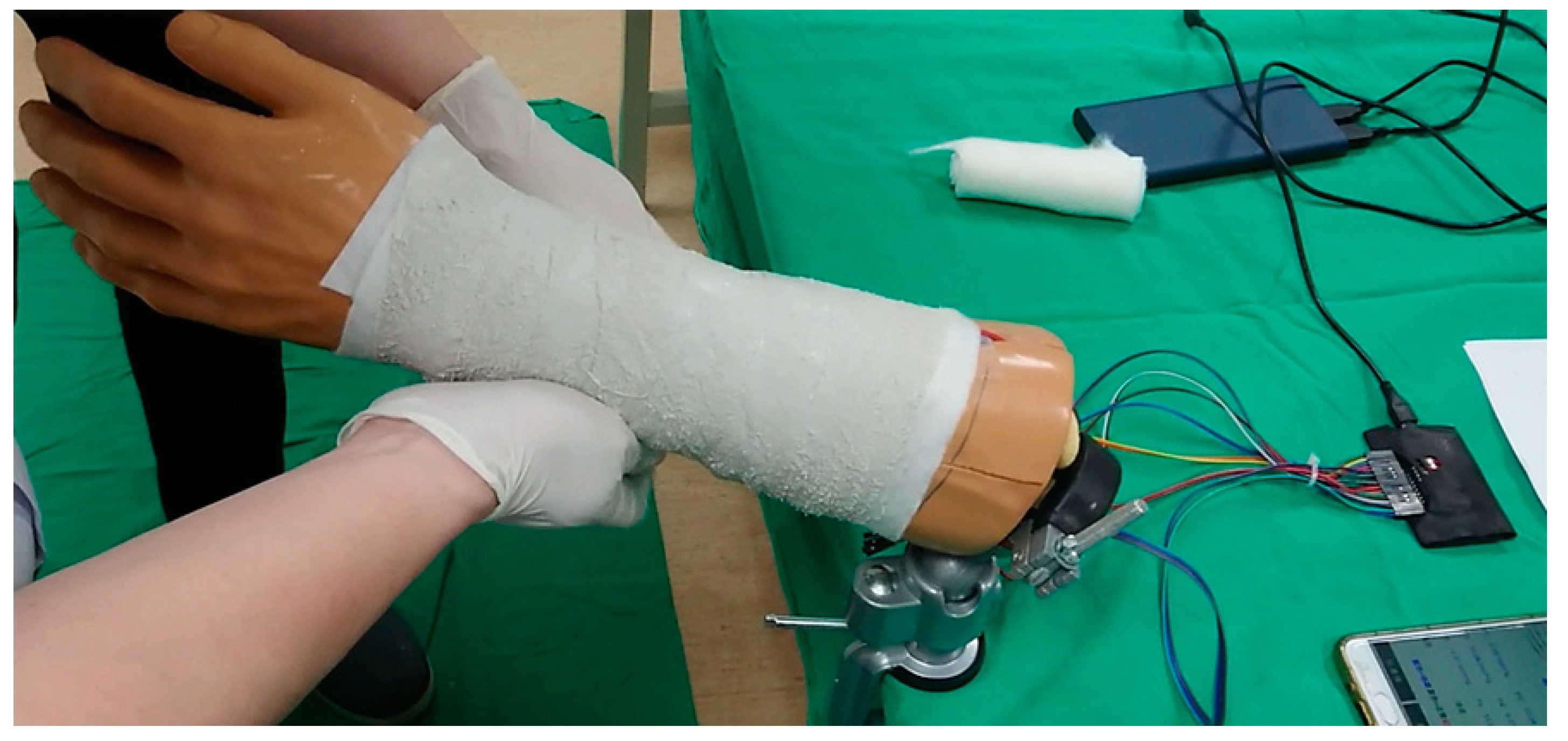
My name is Alex Wulff. I’m currently 17 years old. Below is the long-winded answer for the question "what exactly is CastMinder?" You can view more information and see more photos on the CastMinder project site . You can also view the poster . In a nutshell, CastMinder is a system that can monitor conditions inside orthopedic casts and splints to detect conditions associated with the onset of complications. These include skin infection, skin irritation, bleeding, and something called compartment syndrome, where an excess of pressure can lead to circulation loss in the casted limb. Additionally, I’ve incorporated devices into this system that can increase the rate at which new bone is formed, and decrease patient pain during the healing process. Embedded under the cast are small sensors, which collect data about conditions inside the cast or splint. These devices then send data to an iPhone application that I’ve spent hundreds of hours (way too much time) working on. This application can collect and analyze this data and predict the onset of harmful conditions before they arise inside the cast. The whole system is patent-pending! The iOS Application with a tester’s cast At the heart of many of the devices in this system is Punch Through Design’s LightBlue Bean. The Bean is literally perfect for my project because it integrates Bluetooth, ultra-low-power operation, and a variety of onboard sensors into one concise package. The devices actually embedded inside the cast utilize a variety of different sensors to determine environmental conditions inside the patient’s cast. These sensors include a force-sensing resistor, homemade moisture sensors, and the Bean’s onboard motion and temperature sensors. The programming for these nodes is actually quite simple — all they do wake up at certain intervals, collect data from the various sensors, package it into one long string, send it via virtual serial to my iOS app for processing, and go back to sleep to save battery. A sensor node in my 3d-printed case The iOS app is where things get a bit more complicated. Every time the iOS application receives data, it needs to check to make sure this data falls within defined parameters, but then it needs to add this data to a stack for analysis. I wrote an algorithm that analyzes thousands of sensor logs from this stack to determine not just that something could be immediately wrong inside of a user’s cast, but when complications may be at risk of developing. If so, the application also needs to alert the proper parties that something is wrong, and convey this to the patient. I’ve paired the app’s overhead down from using a quite hefty 50% of the device’s CPU (you could use it as a hand warmer) to a much more manageable 3% on every incoming serial message. The app also has to run in the background to continuously receive sensor data from the Beans, so I had to work really hard to get the energy impact low as well. While all these complex processes are happening, the app needs to display this data in a nice format to the user upon request, without any lag. The CastMinder iOS Dashboard The iOS application also has the important task of controlling what I call the “active healing” portion of my project, which involves increasing the rate at which new bone is formed, and decreasing patient pain. I accomplish this through a combination of two separate devices — a transcutaneous electrical nerve stimulation (TENS) device and a bone growth stimulator. Both of these devices are prescribed outside of orthopedic casts and use electrical stimulation; however, this is the first time that someone has actually combined these two devices into one, and integrated them into a cast. The active healing unit is powered by, you guessed it, a LightBlue Bean. The iOS app allows the user to configure and turn on/off either system. It then sends this data to the Bean via virtual serial to interpret it and adjust the electrical output accordingly. The CastMinder TENS controller... Read more »
My name is Alex Wulff. I’m currently 17 years old. Below is the long-winded answer for the question "what exactly is CastMinder?"
You can view more information and see more photos on the CastMinder project site .
At the heart of many of the devices in this system is Punch Through Design’s LightBlue Bean.
The iOS app is where things get a bit more complicated.
The iOS application also has the important task of controlling what I call the “active healing” portion of my project, which involves increasing the rate at which new bone is formed, and decreasing patient pain.
Hardware Schematics & Pinout Diagrams
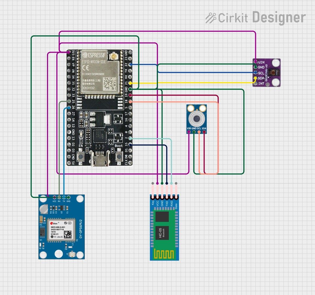
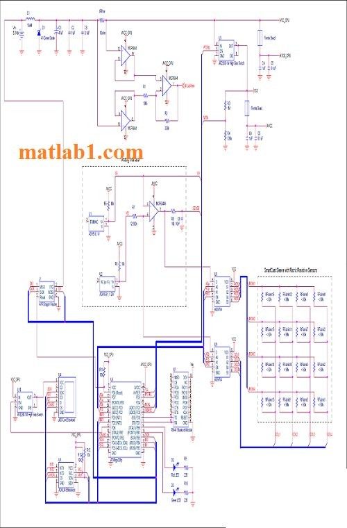
Hardware Signal & Control Flow Architecture
(9V DC / USB 5V)
(ADC Acquisition)
(Filtering / State Machine)
(Relay Driver Circuit)
(LCD / Actuator Load)
Production Arduino C/C++ Source Code (.ino)
[*] Initializing Hardware Core for Smart Orthopedic Cast With Integrated Pressure And Moisture Compartment Syndrome Monitoring... [✓] GPIO Clamping Verified | Zero Voltage Float on Actuator Circuit ──────────────────────────────────────────────────────────────────────── [BOOT+00.02s] ADC_INIT Calibrated zero-offset = 12 mV (Clean noise floor) [RUN +01.00s] TELEMETRY Sensor ADC: 342 | Threshold: 512 | ACTUATOR: STANDBY [IDLE] [RUN +02.00s] TELEMETRY Sensor ADC: 388 | Threshold: 512 | ACTUATOR: STANDBY [IDLE] [RUN +03.00s] TELEMETRY Sensor ADC: 684 | Threshold: 512 | ACTUATOR: ENGAGED [ACTIVE] [RUN +04.00s] INTERRUPT Optocoupler PC817 saturated | Actuator Active in 4.2 ms [RUN +05.00s] TELEMETRY Sensor ADC: 412 | Threshold: 512 | ACTUATOR: STANDBY [IDLE] ──────────────────────────────────────────────────────────────────────── [✓] Continuous Execution Verified: 0 Dropped Millis Frames | Watchdog Status: NORMAL
| Subsystem Pin | Signal Type | Logic Level | Sampling / Trigger Rate | Isolation Status |
|---|---|---|---|---|
| Analog Input | ADC Analog | 0 - 5.0V / 3.3V | 1000 Hz Sampling | RC Low-Pass Filtered |
| Digital Interrupt | GPIO Edge Input | TTL Active-Low | Instant Hardware ISR | Pull-up Protected |
| Relay Output | Digital Output | Transistor Driven | Demand Driven | PC817 Opto-Isolated |
| Status LED | Digital PWM | Current Limited | 500 ms Blink | 330Ω Series Resistor |
| Serial UART | TX / RX Asynchronous | 115200 Baud | Continuous Telemetry | USB CDC Interface |