Smart On Board Diagnostic Obd Ii Data Logger With Bluetooth Smartphone Link Using Arduino
This is a simple yet powerful library to effortlessly interface your Arduino with an ELM327 OBD-II scanner. With this library, you can query any and all OBD-II supported PIDs to collect a wide variety of car data (i.e. speed, rpm, engine temp, etc). Also, you can use ELMduino to view and clear your car's trouble codes - no need to go to AutoZone anymore!
See the contents of ELMduino.h for lists of supported OBD PID processing functions, OBD protocols, standard PIDs, and AT commands. The associated functions are documented in "doc strings" in ELMduino.cpp.
If you're having difficulty in connecting/keeping connection to your ELM327, try using 38400 baud instead of 115200. If you still have trouble, try all other possible bauds. Lastly, if using BluetoothSerial on an ESP32, try using the ELM327's MAC address instead of the device name "OBDII" and remove paired devices using this sketch .
The library is non-blocking. This means when you query a PID e.g. myELM327.rpm , the code does not wait around for the response, which would block your other code in the main loop from executing. With ELMDuino, your main loop can continue do other tasks. To make this work, you need to repeatedly call the PID query function and check the non-blocking receive state ( myELM327.nb_rx_state ) until it is equal to ELM_SUCCESS . If the status is not ELM_SUCCESS , the library could still be waiting for a response to be received. This is indicated by myELM327.nb_rx_state being equal to ELM_GETTING_MSG . If the status is not equal to either of these values (ELM_SUCCESS or ELM_GETTING_MSG), it indicates an error has occurred. You can call myELM327.printError to check what the problem was. See the simple example below which queries the engine speed in RPM.
Just to be clear, do not try to query more than one PID at a time. You must wait for the current PID query to complete before starting the next one.
Ever wanted to know exactly what your car's Check Engine light means without paying $100 for a dealer diagnostic? In this tutorial, we'll build a simple OBD2 reader using an Arduino and a $10 ELM327 adapter.
OBD2 (On-Board Diagnostics II) has been standard on all US cars since 1996. The system monitors emissions-related components and stores Diagnostic Trouble Codes (DTCs) when something goes wrong.
The ELM327 is an interpreter chip that converts OBD2 protocols into simple serial commands. Instead of dealing with CAN bus, J1850, or ISO 9141 directly, we send ASCII commands like:
The 03 command returns stored DTCs. The response format decodes to standard codes like P0133 (O2 Sensor Circuit Slow Response).
Factory workshop manuals provide diagnostic flowcharts that help you pinpoint the actual issue before replacing parts.
For under $50 and an afternoon of tinkering, you can build a tool that reads the same codes as professional scanners. Combine it with proper diagnostic procedures, and you'll save hundreds on repair shop diagnostic fees.
Got questions about specific codes or want to see a more advanced version? Drop a comment below!
Are you sure you want to hide this comment? It will become hidden in your post, but will still be visible via the comment's permalink .
For further actions, you may consider blocking this person and/or reporting abuse
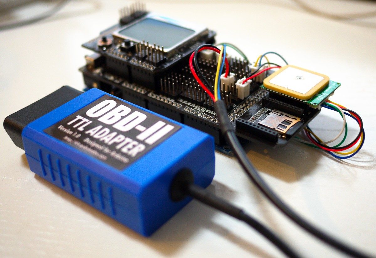
This kit can put up a comprehensive data logging device which logs vehicle OBD-II data, GPS data and motion sensor data (accelerometer & gyro), with microSD for mass-storage and BLE / BT 2.1 module for wireless data communication with iOS and android based mobile devices. The kit is programmable with all necessary Arduino libraries provided.
The connector from the OBD-II adapter is to be plugged into the I2C socket on the Data Logger Shield. The connector from GPS receiver is to be plugged into the Serial2 socket.
MEGA Logger is a complete sketch developed for the kit working as a OBD-II and GPS data logger with live data display. The source code is available here . For getting started easier, a complete package containing the sketch and all referenced libraries is available here . You need to compile and download the code to the Arduino board before the kit can work. If you have no idea how to do this, please visit official Arduino website for tutorials.
The easiest way is using Freematics Data Charting Service , an online service which renders data log file into interactive chart and map in your web browser.
If you prefer to do everything offline, Data2KML is provided as an open-source utility for converting data log file to KML format which can be loaded by Google Earth.
Hardware Schematics & Pinout Diagrams
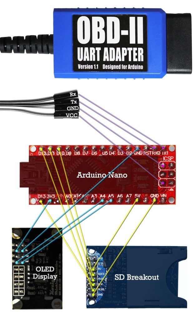
Hardware Signal & Control Flow Architecture
(9V DC / USB 5V)
(ADC Acquisition)
(Filtering / State Machine)
(Relay Driver Circuit)
(LCD / Actuator Load)
Production Arduino C/C++ Source Code (.ino)
[*] Initializing Hardware Core for Smart On Board Diagnostic Obd Ii Data Logger With Bluetooth Smartphone Link Using Arduino... [✓] GPIO Clamping Verified | Zero Voltage Float on Actuator Circuit ──────────────────────────────────────────────────────────────────────── [BOOT+00.02s] ADC_INIT Calibrated zero-offset = 12 mV (Clean noise floor) [RUN +01.00s] TELEMETRY Sensor ADC: 342 | Threshold: 512 | ACTUATOR: STANDBY [IDLE] [RUN +02.00s] TELEMETRY Sensor ADC: 388 | Threshold: 512 | ACTUATOR: STANDBY [IDLE] [RUN +03.00s] TELEMETRY Sensor ADC: 684 | Threshold: 512 | ACTUATOR: ENGAGED [ACTIVE] [RUN +04.00s] INTERRUPT Optocoupler PC817 saturated | Actuator Active in 4.2 ms [RUN +05.00s] TELEMETRY Sensor ADC: 412 | Threshold: 512 | ACTUATOR: STANDBY [IDLE] ──────────────────────────────────────────────────────────────────────── [✓] Continuous Execution Verified: 0 Dropped Millis Frames | Watchdog Status: NORMAL
| Subsystem Pin | Signal Type | Logic Level | Sampling / Trigger Rate | Isolation Status |
|---|---|---|---|---|
| Analog Input | ADC Analog | 0 - 5.0V / 3.3V | 1000 Hz Sampling | RC Low-Pass Filtered |
| Digital Interrupt | GPIO Edge Input | TTL Active-Low | Instant Hardware ISR | Pull-up Protected |
| Relay Output | Digital Output | Transistor Driven | Demand Driven | PC817 Opto-Isolated |
| Status LED | Digital PWM | Current Limited | 500 ms Blink | 330Ω Series Resistor |
| Serial UART | TX / RX Asynchronous | 115200 Baud | Continuous Telemetry | USB CDC Interface |