Smart Low Voltage Underground Cable Fault Distance Locator Using Murray Loop Bridge Automation
A smart cable fault detection tool based on the Wheatstone Bridge principle , enhanced with modern automation for precise and autonomous fault localization.
This project bridges classic electrical principles with modern microcontroller and IoT capabilities. It is ideal for labs, diagnostics, or academic exploration of fault localization systems.
Identifying subterranean cable flaws is essential to maintaining a dependable power distribution system. This project provides a new solution for “Underground Cable Fault Detection Using Arduino,” which focuses on identifying and displaying defects in the cable network.
This project is only demonstrative and cannot be used in actual situations. This project can only, technically, identify line-to-ground problems. It doesn’t need AC power; it just uses DC power. A 5V relay is turned on and off by a digital pin on the Arduino, which regulates each of the aforementioned phases’ operation at a 5V level. Through the use of a resistor and a separate voltage source, the relay eventually prevents the circuit from being completed. The vertical line that represents the ground shortens horizontally with one of the phases when the switch is switched on. A filtered supply is sent to the Arduino’s ADC pin, and the programming may interpret the value as a distance. It is important to know that this project just follows the voltage division rule and does not follow any other principles.
The Arduino code that is supplied is intended for a project that detects faults in underground cables. The code establishes pin connections for three relays (relay1, relay2, relay3), a buzzer, and an analog sensor (A0). It also uses the Liquid Crystal library to drive a 16×2 LCD display. The analog sensor reading and the computed distance are stored in two global variables, read_ADC and distance, respectively. An arrow-like custom symbol is made for the LCD display. Pin modes are configured and a custom LCD character is formed in the setup function. An introductory message appears on the LCD. The primary logic is continually carried out via the loop function. Sequential relay activation is done, and an LCD with arrows indicating the direction of the cable defect are displayed. The software computes the distance, reads data from the analog sensor, and shows the result on the LCD. In the event that a defect is found, the buzzer sounds momentarily. Three simulated cable portions are cycled through while the pattern repeats. The data function is in charge of reading the analog sensor, figuring out how far something is, and sounding the buzzer when a problem is found. Through the LCD and buzzer, the software simulates the identification of problems in various parts of an underground wire, offering both visible and aural feedback. The entire dependability of subterranean cable systems is increased by this approach, which makes it possible to evaluate cable sections for any problems in a methodical and sequential manner.
In today’s rapidly evolving world, underground cables play a crucial role in power distribution systems, telecommunications, and other essential services. However, locating faults in these cables is a significant challenge. To address this, we introduce the “Underground Cable Fault Distance Locator Project” powered by Arduino, an innovative solution for accurately detecting and displaying the fault location in underground cables.
This project is an excellent choice for engineering students, electronics enthusiasts, and professionals looking to implement a practical and impactful idea. Below, we’ll explore its features, components, working principle, and more.
If you are a student who wants to concentrate on understanding the working principle, fault analysis logic, relay operation, and viva preparation rather than assembling and debugging hardware, you can directly use the fully assembled Underground Cable Fault Distance Locator project available on Circuits Bazaar.
Underground cables play a critical role in modern infrastructure, carrying power, data, and communication signals across cities and regions. However, these cables are susceptible to wear and tear, environmental factors, and accidental damage, which can lead to faults. Detecting and repairing these faults quickly is essential to ensure uninterrupted services and prevent costly downtime.
Underground cables are prone to faults caused by weather, excavation, or aging. Unlike overhead lines, detecting these faults is difficult without sophisticated systems. This Arduino-based underground cable fault detector simplifies the process by identifying the fault’s location and distance from the source.
By employing Arduino UNO , an LCD display , and relays , this project provides an easy-to-understand output that aids in quick repair and maintenance, reducing downtime and costs.
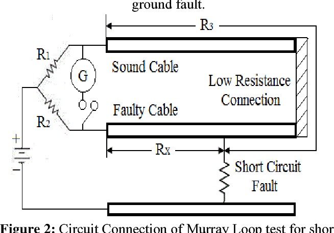
Connect the Varley loop to the Relays and Microcontroller according to the pins mentioned in the Code. here we have shown the single relay but you can take 3 relay as our project required.
Here are the essential components required for building the Underground Cable Fault Distance Locator :
Arduino UNO : The microcontroller forms the brain of the system, handling input and output operations.
After building the circuit and programming the Arduino, it’s crucial to calibrate the system. Calibration involves determining the cable’s velocity factor and the speed of the signal, which are necessary for accurately calculating the fault location.
This project operates based on the principle of Ohm’s Law and the variation in resistance caused by a fault in the cable. Here’s a step-by-step explanation:
Constructing the Arduino-based cable fault locator involves assembling the hardware components, programming the Arduino microcontroller, and connecting the components to the cable.
Connect the 16×2 LCD display to the Arduino board using jumper wires according to the circuits diagram.
Connect the relays pin in the Varley loop circuit to the Arduino board and control pins.
Connect the current-sensing resistors to the relays baord and the Arduino board’s ADC pins.
Write the Arduino sketch to control the relays, read voltage drop values, and calculate the fault location.
Connect one end of the cable to the Arduino board and the other end to the fault injection point.
Connect the voltage-sensing circuits to the respective cable segments using relays.
The Arduino microcontroller will activate the relays one by one, measuring the voltage drop across each cable segment.
Accuracy: Accuracy depends on the calibration of the current-sensing resistors and the precision of the ADC. Fault type: Can only detect short circuit faults; open circuit faults require additional techniques.
Working with high-voltage equipment and electrical circuits demands strict safety measures
Work in a controlled environment. Disconnect power sources when making connections. Use insulating materials and enclosures to prevent electrical hazards. Keep bystanders away from the testing area
The Underground Cable Fault Distance Locator Using Arduino is a smart and innovative project designed to address real-world challenges in cable maintenance. Its cost-effectiveness, accuracy, and scalability make it an ideal choice for engineering students and industry professionals.
By implementing this system, power and communication providers can significantly reduce downtime and maintenance costs, ensuring uninterrupted service delivery.
This innovative project demonstrates the potential of technology to address real-world challenges and contributes to the maintenance and reliability of underground cable networks, ensuring that the world continues to run smoothly.
₹ 4,800.00 Original price was: ₹4,800.00. ₹ 3,800.00 Current price is: ₹3,800.00.
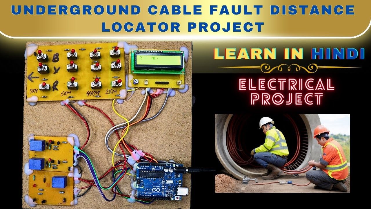
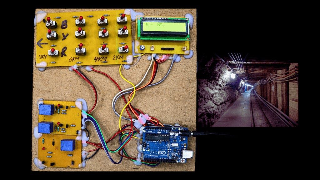
🧠 Underground Cable Fault Distance Locator is a smart electrical engineering project designed to precisely detect and locate cable faults in underground systems like power lines and telephone lines. This ready-to-use project uses a Varley loop circuit , relay driver , and Arduino UNO to detect faults in multiple lines — Red, Yellow, and Blue. The fault distance is displayed on a 16×2 LCD , helping engineers and students to find the exact location of the problem quickly.
🚀 Perfect for B.Tech, Diploma, Polytechnic, ITI & hobbyists , the project is fully assembled on a safe wooden base and includes all essential accessories. This practical system makes fault detection faster, safer, and more accurate compared to traditional methods.
🚀 The Underground Cable Fault Distance Locator is an advanced electrical engineering project designed to detect and locate faults in underground power and telephone cables quickly and accurately.
This ready-to-use project uses a Varley loop circuit along with Arduino Uno , relay drivers , and a 16×2 LCD display to pinpoint the exact location of cable faults on Red, Yellow, and Blue lines. The fault distance is displayed directly on the LCD screen, making troubleshooting fast, safe, and efficient ⚡.
Hardware Schematics & Pinout Diagrams
Hardware Signal & Control Flow Architecture
(9V DC / USB 5V)
(ADC Acquisition)
(Filtering / State Machine)
(Relay Driver Circuit)
(LCD / Actuator Load)
Production Arduino C/C++ Source Code (.ino)
[*] Initializing Hardware Core for Smart Low Voltage Underground Cable Fault Distance Locator Using Murray Loop Bridge Automation... [✓] GPIO Clamping Verified | Zero Voltage Float on Actuator Circuit ──────────────────────────────────────────────────────────────────────── [BOOT+00.02s] ADC_INIT Calibrated zero-offset = 12 mV (Clean noise floor) [RUN +01.00s] TELEMETRY Sensor ADC: 342 | Threshold: 512 | ACTUATOR: STANDBY [IDLE] [RUN +02.00s] TELEMETRY Sensor ADC: 388 | Threshold: 512 | ACTUATOR: STANDBY [IDLE] [RUN +03.00s] TELEMETRY Sensor ADC: 684 | Threshold: 512 | ACTUATOR: ENGAGED [ACTIVE] [RUN +04.00s] INTERRUPT Optocoupler PC817 saturated | Actuator Active in 4.2 ms [RUN +05.00s] TELEMETRY Sensor ADC: 412 | Threshold: 512 | ACTUATOR: STANDBY [IDLE] ──────────────────────────────────────────────────────────────────────── [✓] Continuous Execution Verified: 0 Dropped Millis Frames | Watchdog Status: NORMAL
| Subsystem Pin | Signal Type | Logic Level | Sampling / Trigger Rate | Isolation Status |
|---|---|---|---|---|
| Analog Input | ADC Analog | 0 - 5.0V / 3.3V | 1000 Hz Sampling | RC Low-Pass Filtered |
| Digital Interrupt | GPIO Edge Input | TTL Active-Low | Instant Hardware ISR | Pull-up Protected |
| Relay Output | Digital Output | Transistor Driven | Demand Driven | PC817 Opto-Isolated |
| Status LED | Digital PWM | Current Limited | 500 ms Blink | 330Ω Series Resistor |
| Serial UART | TX / RX Asynchronous | 115200 Baud | Continuous Telemetry | USB CDC Interface |