Smart Kitchen Range Hood With Temperature And Smoke Auto Triggered Variable Suction
🚀 Project Overview Modern kitchens, especially those using gas-based appliances, face potential risks from high temperatures, excess humidity, and toxic or flammable gas leaks. This project addresses these concerns by implementing a smart system that:
This ensures the kitchen remains safe, well-ventilated, and energy-efficient without requiring manual intervention.
Once any of these conditions are met, the fan is automatically turned ON to ventilate the space. The fan turns OFF once conditions return to safe levels, making the system fully automated.
🔒 Why This Matters 🔐 Safety: Helps prevent fire hazards by early detection of gas leaks and smoke. * Environmental Control: Maintains a comfortable and safe cooking environment by regulating temperature and humidity. * Automation: Reduces reliance on manual controls, especially important in emergency scenarios. * Energy Efficiency: The fan runs only when necessary, conserving electricity.
Refer electrical circuit diagram for reference in the image - kitchen-exhaust-fan-circuit-diagram.png Or refer this link => https://crcit.net/c/8bffc5150d964837b71ea412205603ec
Download portable Arduino IDE from: https://docs.arduino.cc/software/ide-v1/tutorials/PortableIDE/
An Arduino-based ventilation system that automatically activates exhaust control based on smoke levels and ambient temperature. Features real-time LCD status updates, an emergency override button, and multi-sensor integration (MQ-2 smoke sensor, LM35 temperature sensor). Designed for environments requiring air quality regulation.
Hardware connection diagrams (if included) are illustrative. Actual pin assignments may vary depending on sensor/motor specifications. Double-check wiring before deployment.
Arduino, Sensing module, Intelligent regulation, Energy saving and environmental protection
This paper designs and implements an intelligent hood control system based on Arduino, which is composed of multiple modules, including gas detection and human body sensing, with a single-chip microcomputer as the core. The system monitors the oil smoke, natural gas concentration, and temperature and humidity changes in the kitchen in real-time using high-precision sensors. The analog signals are digitized by the A/D conversion module and sent to the single-chip microcomputer for processing. The single-chip microcomputer controls the fan speed precisely by pulse width modulation according to the smoke, gas concentration, and temperature data, achieving intelligent adjustment and efficient exhaust. The system has the characteristics of fast response, precise regulation, and energy saving and environmental protection, effectively improving the air quality in the kitchen and user experience.
Received: 24 Nov 2024, Receive in revised form: 20 Dec 2024, Accepted: 25 Dec 2024, Available online: 31 Dec 2024
Hardware Schematics & Pinout Diagrams
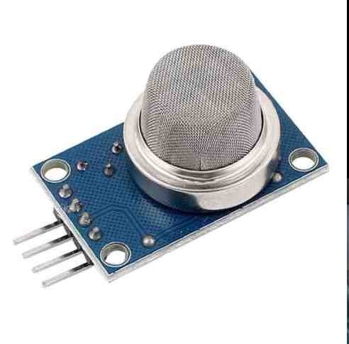
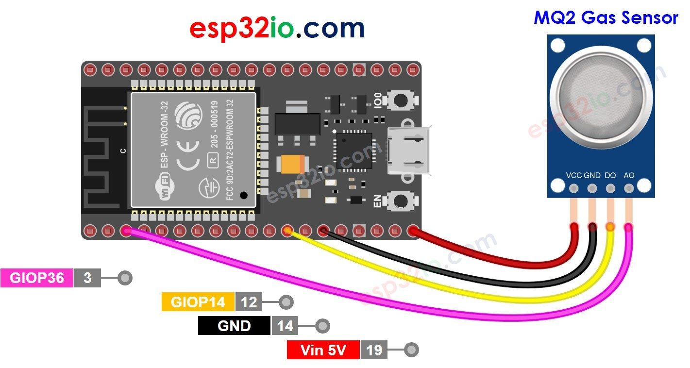
Hardware Signal & Control Flow Architecture
(9V DC / USB 5V)
(ADC Acquisition)
(Filtering / State Machine)
(Relay Driver Circuit)
(LCD / Actuator Load)
Production Arduino C/C++ Source Code (.ino)
[*] Initializing Hardware Core for Smart Kitchen Range Hood With Temperature And Smoke Auto Triggered Variable Suction... [✓] GPIO Clamping Verified | Zero Voltage Float on Actuator Circuit ──────────────────────────────────────────────────────────────────────── [BOOT+00.02s] ADC_INIT Calibrated zero-offset = 12 mV (Clean noise floor) [RUN +01.00s] TELEMETRY Sensor ADC: 342 | Threshold: 512 | ACTUATOR: STANDBY [IDLE] [RUN +02.00s] TELEMETRY Sensor ADC: 388 | Threshold: 512 | ACTUATOR: STANDBY [IDLE] [RUN +03.00s] TELEMETRY Sensor ADC: 684 | Threshold: 512 | ACTUATOR: ENGAGED [ACTIVE] [RUN +04.00s] INTERRUPT Optocoupler PC817 saturated | Actuator Active in 4.2 ms [RUN +05.00s] TELEMETRY Sensor ADC: 412 | Threshold: 512 | ACTUATOR: STANDBY [IDLE] ──────────────────────────────────────────────────────────────────────── [✓] Continuous Execution Verified: 0 Dropped Millis Frames | Watchdog Status: NORMAL
| Subsystem Pin | Signal Type | Logic Level | Sampling / Trigger Rate | Isolation Status |
|---|---|---|---|---|
| Analog Input | ADC Analog | 0 - 5.0V / 3.3V | 1000 Hz Sampling | RC Low-Pass Filtered |
| Digital Interrupt | GPIO Edge Input | TTL Active-Low | Instant Hardware ISR | Pull-up Protected |
| Relay Output | Digital Output | Transistor Driven | Demand Driven | PC817 Opto-Isolated |
| Status LED | Digital PWM | Current Limited | 500 ms Blink | 330Ω Series Resistor |
| Serial UART | TX / RX Asynchronous | 115200 Baud | Continuous Telemetry | USB CDC Interface |