Smart Home Electricity Tamper And Neutral Disconnection Detector With Trip Isolation Relay
In this project tutorial, we will design, construct, and program an IoT tamper-proof energy meter using Arduino and WiFi LAN dashboard. This project’s research aims to design and model an energy meter with a Wi-Fi-based anti-theft/tamper mode that precisely measures the power consumed, detects tampering activity, and notifies the authorized personnel through SMS or Email.
The Single phase energy module PZEM as shown in the picture above is connected with having its current transformer running through the Live wire of the Public Utility Input. This current transformer is responsible for sensing the amount of current consumes by the Load.
The PZEM module is programmed via serial communication protocol. This connection is made to read the load voltage, open voltage, power factor once the MCU is connected to the module. To program this module, the connection is made as shown above. We used the Arduino IDE to program the energy module.
The source code written above also contains HTML, CSS and a little bit of Javascript functions. The whole source code aims at promoting the WiFi LAN based dashboard where the user and admin can monitor the project remotely.
The picture diagram above shows the Bare minimum source code (also called sketch) on the Arduino Software IDE. It illustrates only two functions: the setup function and the loop function. This program code is used to reset every module to it has nothing running inside previously. Hence we applied this also here. The setup function runs any program which is within it once and proceeds to the function while the loop function runs any command or syntax placed within it repeatedly. The setup function was used as shown below to set the baudrate (communication speed) between the personal computer (PC) and the microcontroller.
The program code began with calling the vital libraries (important pieces of code needed in the program). These libraries are the Softwareserial library and the PZEM library. The former tells the complier that we are using the software serial method for communication with the PZEM module rather than the hardware. This means that we are defining our own pins for the serial communication pins; namely, the Receiver and Transmitter pins (this is shown in code line 24 and 25 respectively). We called the PZEM library to make used of its function syntax. Which is shown how it is passed to serial communication in code line 29 and 30. As mentioned above, the serial communication is set to 115200 baudrate in the function setup at code line 24.
The function begins with printing the hexadecimal address of the PZEM module and the AC voltage read by the sensor in floating variable. Other AC power parameter was also read by the sensor. These were current, power, energy, frequency and power factor (PF). This is shown in code line 42 through 48. We used an if condition to check when there was error reading any of the parameters. This was to be displayed on the Serial monitor. However if there wasn’t any error in reading any of the above parameters, the parameters read would be displayed using the else statement condition shown in code line 66 through 71.
The 2004 LCD was interfaced to the design as shown in the figure above; using the Intra-Intra Circuit (I2C). This is very possible using I2C LCD module. It allowed us to communicate to the LCD module using 2-wire method rather than the 4-wire data or 8-wire data method. This 2-wire method are the Serial Data (SDA) and the Serial Clock (SCL) wire.
This allowed us to use the I2C backlight function to turn on the LED of the LCD module and print a display of welcome message. And cleared the LCD screen after 3 seconds of displaying the message. The loop displays the parameters on the LCD module. This si shown in code line 89 through 110. The syntax makes use of cursor position in its lcd.setCursor function. This means that the LCD was segmented into rows and columns. The first row was row 0. And since it was a 20×4 LCD module, the last row was row 3. The print function prints string data type or character to where the cursor is placed.
When powered the LCD displays the name of the user and a welcome message. and it will also display the project name and energy parameters that are metered.
The system was needed detect theft by noticing when a user has tampered with it by opening the casing. To get this done, we used a pushbutton which we placed at the top of the case cover as shown in the diagram below.
The program allowed us to detect intrusion as one would open the meter when it is powered. As the system was meant to be placed on High tension distribution pole. The opening would mean that the user would want to bypass the legal output channel to avoid paying for bills.
However, this mechanism of theft demanded we attached a 3.3V LiPo battery to keep the system on even when there is no Utility supply. This battery is recharged when the Utility supply returns. The downside to this method is that if the Utility supply is not restored for a long period of time, the battery dies of overuse and undercharged state.
To solve this problem, we had to think of way to use an RTC (real time clock) module. This was able to keep the time and wait for a system mode of No Power. Each RTC chip comes with an external battery that allows it to keep time even when the design it is connected to goes offline. This external battery was removed and the and the RTC was powered directly by the utility supply via the power supply. When the device is being tampered with, the pushbutton would go into tamper mode and the RTC would record the power interruption.
Here is the WiFI dashboard of the project displayed on a mobile port. The source code above has web development script of HTML that renders the code to produce such and interface as shown here. It also has inline CSS and a little bit of JS code. Once the user connects to the LAN WiFi, he or she can go to the IP address and see these web results.
And this is the admin dashboard. For the admin, he can log in and with his secured login details and do some admin functions. like reset the meter and if the user has tampered with the meter, and it is locked, he could swipe the tampered mode and restart the meter.
So far we have designed and constructed an IoT tamper-proof energy meter. For us to send these values to the cloud, we will add the Cayenne libraries and export the measured and metered energy parameters to Cayenne mydevices designed dashboard. See this project on how to do that. The Cayenne dashboard will also allow us to set notifications or alerts in the form of email or SMS depending on the factors we set for. Leave us a comment about what you think about the project design.
I decided to create a Smart AC watt-hour meter after experiencing a spike in my electricity bill that left me both shocked and curious. Each month, I tried to be mindful of my energy use, but I realized I had no clear way to track which appliances were consuming the most power or when. I also noticed that many homes and businesses around me faced similar challenges, unaware of their real-time energy usage, leading to unnecessary expenses and often wasting power.
With my interest in electronics and IoT, I knew I could build a solution to monitor power consumption accurately. I wanted to design a device that could give me real-time feedback on voltage, current, power, and even environmental conditions, like temperature and humidity, that might affect energy usage. I also wanted to be able to access this information remotely, so I integrated Wi-Fi, allowing data to be monitored and controlled via an online dashboard.
Adding safety features was crucial. I included a vibration sensor and magnet sensor to detect tampering, a flame sensor for fire alerts, and a relay to remotely shut off when needed. This project quickly turned into more than just a personal need; it became a tool I could offer to others to manage energy responsibly.
Creating this Smart AC watt-hour meter has been incredibly fulfilling. Not only am I reducing my own energy costs, but I'm also contributing to a sustainable approach to power usage—one smart meter at a time.
CircuitDigest gave 3 different MCU boards to choose from for building my project. I chose the Arduino Uno R4 WiFi for my Smart AC Meter project due to several key features that make it ideal for IoT and data-intensive applications like this.
Powerful Processor: It’s powered by the Renesas RA4M1 32-bit ARM Cortex-M4 running at 48 MHz. This provides significantly more processing power than traditional Arduino boards, which is essential for accurately calculating power, energy, and handling real-time data.
Hardware Schematics & Pinout Diagrams
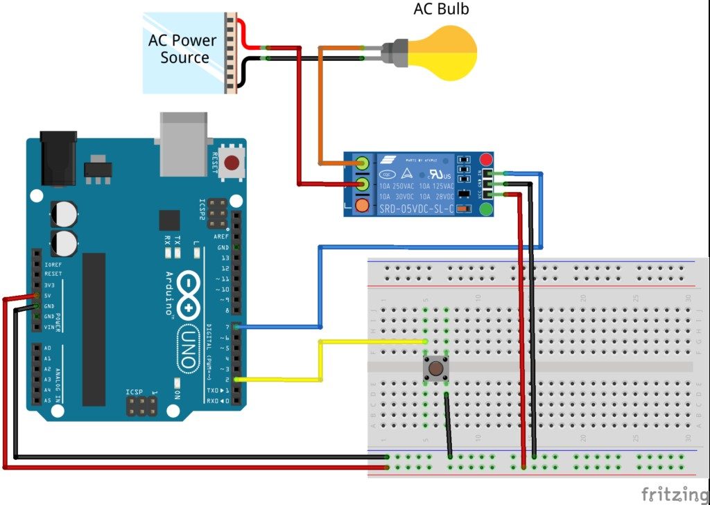
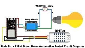
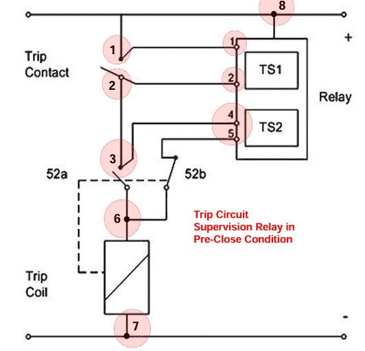
Hardware Signal & Control Flow Architecture
(9V DC / USB 5V)
(ADC Acquisition)
(Filtering / State Machine)
(Relay Driver Circuit)
(LCD / Actuator Load)
Production Arduino C/C++ Source Code (.ino)
[*] Initializing Hardware Core for Smart Home Electricity Tamper And Neutral Disconnection Detector With Trip Isolation Relay... [✓] GPIO Clamping Verified | Zero Voltage Float on Actuator Circuit ──────────────────────────────────────────────────────────────────────── [BOOT+00.02s] ADC_INIT Calibrated zero-offset = 12 mV (Clean noise floor) [RUN +01.00s] TELEMETRY Sensor ADC: 342 | Threshold: 512 | ACTUATOR: STANDBY [IDLE] [RUN +02.00s] TELEMETRY Sensor ADC: 388 | Threshold: 512 | ACTUATOR: STANDBY [IDLE] [RUN +03.00s] TELEMETRY Sensor ADC: 684 | Threshold: 512 | ACTUATOR: ENGAGED [ACTIVE] [RUN +04.00s] INTERRUPT Optocoupler PC817 saturated | Actuator Active in 4.2 ms [RUN +05.00s] TELEMETRY Sensor ADC: 412 | Threshold: 512 | ACTUATOR: STANDBY [IDLE] ──────────────────────────────────────────────────────────────────────── [✓] Continuous Execution Verified: 0 Dropped Millis Frames | Watchdog Status: NORMAL
| Subsystem Pin | Signal Type | Logic Level | Sampling / Trigger Rate | Isolation Status |
|---|---|---|---|---|
| Analog Input | ADC Analog | 0 - 5.0V / 3.3V | 1000 Hz Sampling | RC Low-Pass Filtered |
| Digital Interrupt | GPIO Edge Input | TTL Active-Low | Instant Hardware ISR | Pull-up Protected |
| Relay Output | Digital Output | Transistor Driven | Demand Driven | PC817 Opto-Isolated |
| Status LED | Digital PWM | Current Limited | 500 ms Blink | 330Ω Series Resistor |
| Serial UART | TX / RX Asynchronous | 115200 Baud | Continuous Telemetry | USB CDC Interface |