Smart Greenhouse Environment Management System Utilizing Dual Axis Ventilation And Arduino Mega
Introducing the "Smart Greenhouse" : an Arduino based system designed to automatically monitor environmental conditions of a greenhouse and react accordingly.
It controls irrigation, ventilation and user feedback by combining soil moisture sensing, temperature and humidity monitoring, a water pump, a stepper driven greenhouse door, an LCD display and RGB LED indicators.
The goal of the project is to demonstrate how embedded systems can be used to automate real world agricultural processes using a combination of sensors and non-blocking logic.
The system is built around an Arduino board (Arduino Uno or compatible). The following components are required:
The system is built around an Arduino Uno, which acts as the central controller for all sensors. All components are mounted on a breadboard.
The soil moisture sensor is connected to the Arduino using three wires: VCC and GND provide power, while the analog output is connected to analog pin A0. This sensor continuously measures soil humidity and provides analog values that are later converted into percentage values by the software.
A DHT11 temperature and humidity sensor is connected to digital pin 2 and powered directly from the Arduino. This sensor is used to monitor the internal greenhouse environment and provides both temperature and humidity readings.
An NTC thermistor is used to measure the external temperature. It is wired in a voltage divider configuration with a fixed resistor (10kΩ) and connected to analog pin A1.
The irrigation system is controlled through a relay module. The relay input pin is connected to digital pin 4, while the relay contacts control the power supplied to the water pump.
A 16x2 LCD display is connected using digital pins 8 to 13. A potentiometer is used to adjust the display contrast. The LCD provides real time feedback to the user, showing temperature, humidity, soil moisture, and pump status across different screens.
A push button connected to digital pin 3 allows the user to switch between LCD screens.
An RGB LED is connected to digital pins 5 (red), 6 (green), and 7 (blue) and is used as a visual indicator for system status, such as pump activity and greenhouse door movement.
The greenhouse "ventilation mechanism" is implemented using a stepper motor driven through a ULN2003 driver board . The stepper motor is connected to analog pins A2 to A5 and is used to open or close the greenhouse door automatically based on the internal temperature.
A complete wiring diagram is shown in the image above and reflects the actual prototype used during development and testing.
After powering up the project, the system waits 2 seconds and the greenhouse enters automatic mode.
The pump turns ON when the soil moisture drops below 10% and it turns OFF when the moisture rises above 55%. The use of two different threshold is needed to prevent rapid oscillations and ensure a stable system behavior, although they can be customized according to the preferred moisture level of the soil.
The stepper motor controls the greenhouse door allowing proper ventilation and stabilization of temperatures. When the temperature rises above 25°C the door opens, when it goes below 15°C the door closes.
During the development of the project, a simple 3D model of the greenhouse was created to help with the design and prototyping phase. The main goal of this model was to better understand the overall structure, check the dimensions, and test the movement of the automated door.
Each member actively participated in the development and testing phases of the project.
Smart Greenhouse is an embedded software and IoT project featuring automatic irrigation, temperature control and ventilation.
A robust, microcontroller-based automation system designed to monitor and regulate environmental parameters in modern greenhouses. This system optimizes resource consumption (water and energy) while ensuring optimal plant growth conditions.
An Arduino-based automated greenhouse management system featuring environmental sensing, real-time LCD display, and Bluetooth manual override.
An Arduino smart greenhouse project is an automation system in which an Arduino or ESP32 measures the air temperature, humidity, soil moisture and light in a greenhouse and runs the fan, heater, water pump and grow lights on its own. It's one of the most popular topics for science fairs, school competitions and technology classes because the result is easy to see: the pump starts when the soil dries out, the fan spins when it gets hot inside, and the LEDs come on in the evening. Better still, there's almost no difference in circuit or code between a model greenhouse built from a storage box and a real mini greenhouse on your balcony.
In this guide we start with what plants actually need, then build the model greenhouse step by step: the parts list and rough cost, wiring the sensors (DHT22, capacitive soil moisture sensor, LDR) and the actuators (fan, heater, pump and LEDs via relays and a MOSFET), the power plan and the pin table. Next we explain the threshold and hysteresis logic that stops the relays from clicking constantly, the complete Arduino code without delay, and the 16x2 LCD. In the final sections you'll find how to monitor the greenhouse from your phone with an ESP32 , a MicroPython version for the Raspberry Pi Pico , tips for school and science-fair presentations, and common mistakes.
Every smart greenhouse runs the same four-step loop: measure, decide, act, display . The sensors measure the environment: how warm is it inside, how humid is the air, has the soil dried out, is there enough light? The Arduino compares these values with the rules you set: “if the temperature goes above 30 °C, run the fan”, “if soil moisture drops below 35%, water”. The actuators carry out the decision: relays switch the fan, heater and pump on and off, and a MOSFET sets the brightness of the LED strip. Finally, the LCD and your phone show you the current state of the greenhouse. The climate computers in real commercial greenhouses work with exactly this loop; they just use more sensors and bigger motors.
Before you write any rules, you need to know what you're aiming for. Most plants want different temperatures by day and by night; cooling down a little at night helps the plant rest. If the humidity stays above 85% for long periods, water condenses on the leaves and fungal diseases such as mould and downy mildew spread quickly; that's why the fan in a greenhouse runs not only to cool things down but also to get rid of humidity. As for light, most vegetable seedlings want 14–16 hours a day, but they also need a dark period of at least 6–8 hours; leaving the LEDs on all night does the plant more harm than good. The values below are a good starting guide; adjust them for whatever you're growing.
The easiest and cheapest enclosure is a clear plastic storage box with a lid : a 40–60 litre box is enough for two or three pots, it's waterproof, and it's easy to drill with a craft knife or a heated tip. If you want a more realistic look, build a frame from wooden strips and clad it with 2–3 mm clear acrylic (Plexiglas) or PETG sheets; a greenhouse with a pitched roof looks much better at a presentation. Around 50×35×40 cm is a good starting size. Whichever enclosure you choose, the lid or one side wall has to open; you'll be reaching inside to water plants, move the sensor and tidy up cables.
Prices vary a lot between sellers, so here's a rough budget rather than exact figures. Excluding the board, the basic version (DHT22, soil moisture sensor, LDR, 2-channel relay, pump and a 5 V fan) usually costs around 25–40 dollars. The full version with the heater, LED strip, LCD, 12 V adapter, LM2596, float switch and enclosure usually comes to about 70–120 dollars; most of the budget goes on the board, the adapter, the display and the enclosure. If you have an Arduino starter kit , the board, breadboard, wires, LDR, resistors and often the LCD are already covered. On a tight budget, leave the heater and LEDs for a second stage; watering and ventilation on their own already make a meaningful, working project.
We recommend the DHT22 (AM2302) for a greenhouse. It costs a little more than the DHT11, but it measures temperature from −40 to 80 °C to ±0.5 °C and humidity across 0–100% to about ±2%; the DHT11 is only accurate to ±2 °C between 0 and 50 °C and can't see humidity above 90%. Since a greenhouse can go above 90% humidity in the morning and below freezing in winter, the DHT22 is a much better fit. The sensor can take a reading at most once every 2 seconds , so the code reads it every 2.5 seconds. If you put the sensor where the sun or the LEDs shine directly on it, its body heats up and it reads a few degrees above the air temperature; shading it with a white cover with holes prevents this. Wiring and library details are in the DHT11 and DHT22 temperature and humidity sensor article.
Hardware Schematics & Pinout Diagrams
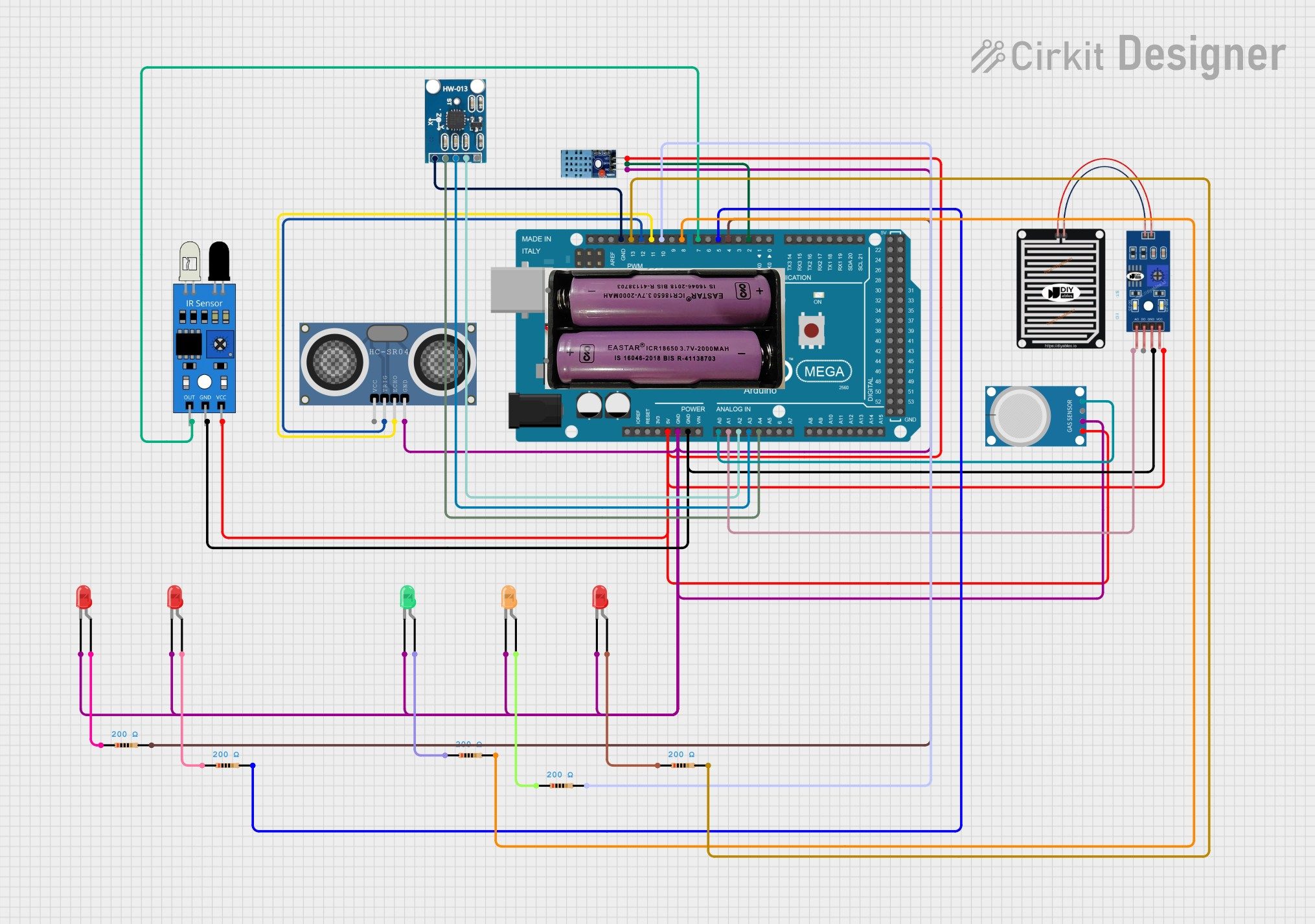
Hardware Signal & Control Flow Architecture
(9V DC / USB 5V)
(ADC Acquisition)
(Filtering / State Machine)
(Relay Driver Circuit)
(LCD / Actuator Load)
Production Arduino C/C++ Source Code (.ino)
[*] Initializing Hardware Core for Smart Greenhouse Environment Management System Utilizing Dual Axis Ventilation And Arduino Mega... [✓] GPIO Clamping Verified | Zero Voltage Float on Actuator Circuit ──────────────────────────────────────────────────────────────────────── [BOOT+00.02s] ADC_INIT Calibrated zero-offset = 12 mV (Clean noise floor) [RUN +01.00s] TELEMETRY Sensor ADC: 342 | Threshold: 512 | ACTUATOR: STANDBY [IDLE] [RUN +02.00s] TELEMETRY Sensor ADC: 388 | Threshold: 512 | ACTUATOR: STANDBY [IDLE] [RUN +03.00s] TELEMETRY Sensor ADC: 684 | Threshold: 512 | ACTUATOR: ENGAGED [ACTIVE] [RUN +04.00s] INTERRUPT Optocoupler PC817 saturated | Actuator Active in 4.2 ms [RUN +05.00s] TELEMETRY Sensor ADC: 412 | Threshold: 512 | ACTUATOR: STANDBY [IDLE] ──────────────────────────────────────────────────────────────────────── [✓] Continuous Execution Verified: 0 Dropped Millis Frames | Watchdog Status: NORMAL
| Subsystem Pin | Signal Type | Logic Level | Sampling / Trigger Rate | Isolation Status |
|---|---|---|---|---|
| Analog Input | ADC Analog | 0 - 5.0V / 3.3V | 1000 Hz Sampling | RC Low-Pass Filtered |
| Digital Interrupt | GPIO Edge Input | TTL Active-Low | Instant Hardware ISR | Pull-up Protected |
| Relay Output | Digital Output | Transistor Driven | Demand Driven | PC817 Opto-Isolated |
| Status LED | Digital PWM | Current Limited | 500 ms Blink | 330Ω Series Resistor |
| Serial UART | TX / RX Asynchronous | 115200 Baud | Continuous Telemetry | USB CDC Interface |