Smart Fire Safety System With Automated Electrical Mains Disconnection And Sprinkler Solenoids
The Arduino Smart Fire Extinguishing System is an intelligent embedded safety project designed to automatically detect fire and flammable gas leakage while taking immediate protective actions without human intervention.
The project improves safety in homes, laboratories, warehouses and industrial environments.
This project is developed by Tanvir Hussain for his school exhibition in the year 2025.
Made with ❤️ using Arduino HydrogenGo - View Our Website 🔥 Stay Safe • Detect Early • Respond Automatically 🚒
🔥 Arduino-based smart fire extinguishing and gas detection system using three flame sensors and an MQ-6 gas sensor. Automatically extinguishes fire with a water pump and servo, triggers alarms, switches off main AC power, and activates emergency DC lighting for enhanced safety.
this is a smart fire protection system it helps us in telling where is the fire . This project works like when the fire is on any floor the gas sensor will alert us the buzzer will start to buzz and the bulb will start to glow and the sprinkler motor will be extinguishing the fire and the exhaust motor will be taking out the smoke from the building and also a neopixel LED will be there on the door because there is zero visibility in the smoke so the greenlight will show us the way out this is how it works
An Arduino-based embedded system that detects smoke in real time and responds automatically — triggering an alarm and activating a water pump to suppress a fire before it spreads.
Developed for SET111: Digital Design , Software Engineering Department, Egyptian Chinese University. Supervised by Dr. Islam Mohamed · Submitted 22 December 2024
Fire safety is a critical concern in both residential and industrial environments, where timely detection and response can prevent severe damage and save lives. Conventional fire detection systems typically rely on smoke detectors and alarms to warn occupants of danger, but they lack an integrated mechanism to actively respond to the fire itself. This project addresses that gap with an Automated Fire Suppression and Alert System — a low-cost embedded solution that combines real-time smoke detection with automated water-based suppression and an audible alarm, enabling early warning and immediate intervention against small fires before they escalate.
The system continuously monitors the surrounding air for smoke particles. When smoke is detected above a set threshold, it simultaneously:
This closed-loop response — detect, alert, and act — is what distinguishes the system from a conventional smoke alarm.
The control logic, implemented in flame.ino , follows a simple detect-and-respond loop:
Note: The sensor's HIGH/LOW logic should be verified against the MQ2 module's threshold configuration (set via its onboard potentiometer) before deployment, to confirm which state corresponds to smoke detection.
The full wiring schematic — showing sensor, relay, pump, buzzer, and Arduino connections — is included in the project report ( SET111-REPORT__APA_Format.docx ).
An Arduino-based smart system designed for early fire detection, automated water suppression, and alarm mechanisms using an MQ-2 smoke sensor, 5V relay module, mini water pump, and buzzer to handle small fires before they escalate
This is the Pseudo code for the project which shows how the project is supposed to be implemented. It is gives the user a step by step idea on how the project works.
This is the flowchart for the project and gives a general idea on what the Home Safety System should do and how it performs
This is the EAGLE schematic for the circuit which shows h=all the proper connections of each component to the Arduino Uno
Hardware Schematics & Pinout Diagrams
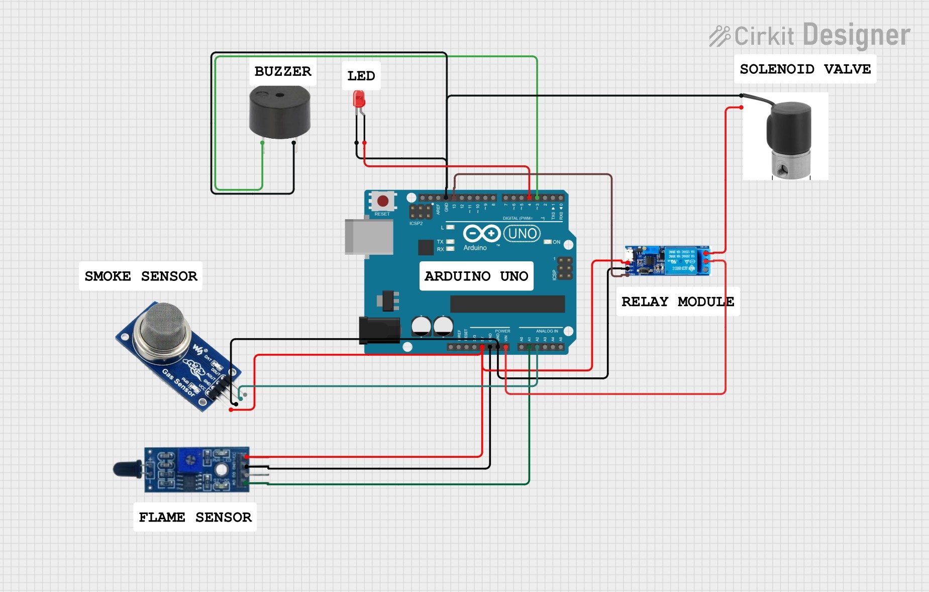
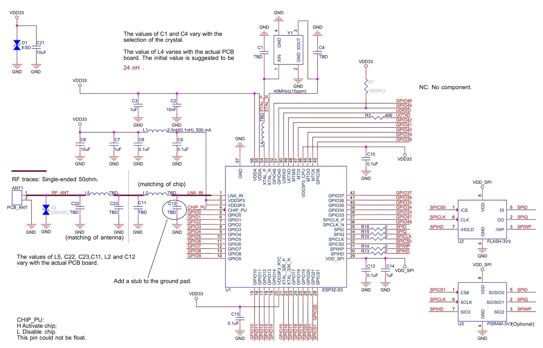
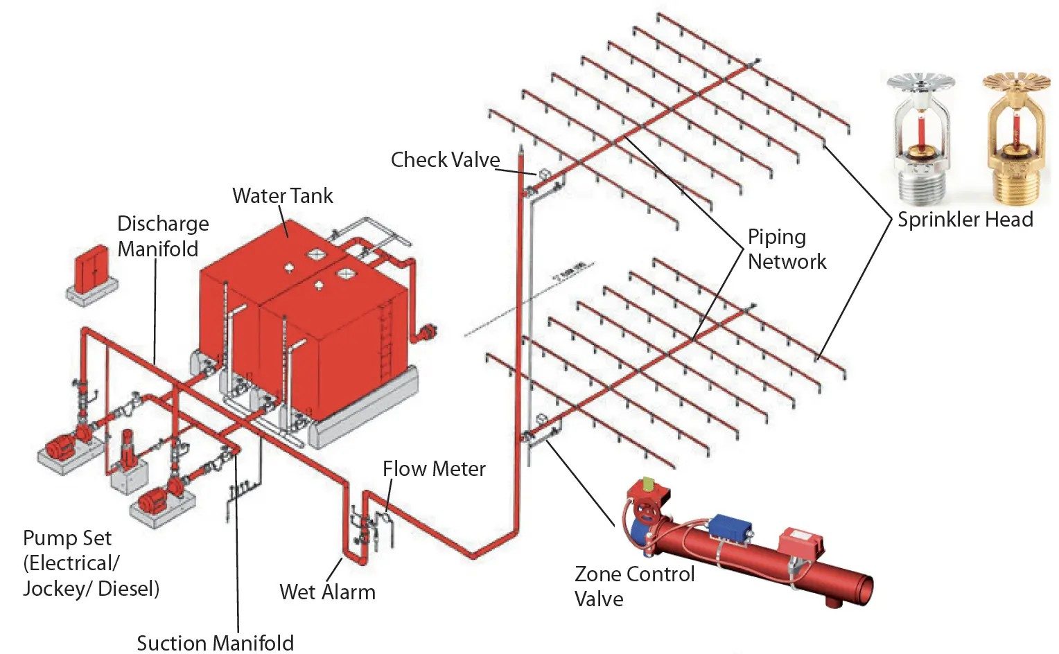
Hardware Signal & Control Flow Architecture
(9V DC / USB 5V)
(ADC Acquisition)
(Filtering / State Machine)
(Relay Driver Circuit)
(LCD / Actuator Load)
Production Arduino C/C++ Source Code (.ino)
[*] Initializing Hardware Core for Smart Fire Safety System With Automated Electrical Mains Disconnection And Sprinkler Solenoids... [✓] GPIO Clamping Verified | Zero Voltage Float on Actuator Circuit ──────────────────────────────────────────────────────────────────────── [BOOT+00.02s] ADC_INIT Calibrated zero-offset = 12 mV (Clean noise floor) [RUN +01.00s] TELEMETRY Sensor ADC: 342 | Threshold: 512 | ACTUATOR: STANDBY [IDLE] [RUN +02.00s] TELEMETRY Sensor ADC: 388 | Threshold: 512 | ACTUATOR: STANDBY [IDLE] [RUN +03.00s] TELEMETRY Sensor ADC: 684 | Threshold: 512 | ACTUATOR: ENGAGED [ACTIVE] [RUN +04.00s] INTERRUPT Optocoupler PC817 saturated | Actuator Active in 4.2 ms [RUN +05.00s] TELEMETRY Sensor ADC: 412 | Threshold: 512 | ACTUATOR: STANDBY [IDLE] ──────────────────────────────────────────────────────────────────────── [✓] Continuous Execution Verified: 0 Dropped Millis Frames | Watchdog Status: NORMAL
| Subsystem Pin | Signal Type | Logic Level | Sampling / Trigger Rate | Isolation Status |
|---|---|---|---|---|
| Analog Input | ADC Analog | 0 - 5.0V / 3.3V | 1000 Hz Sampling | RC Low-Pass Filtered |
| Digital Interrupt | GPIO Edge Input | TTL Active-Low | Instant Hardware ISR | Pull-up Protected |
| Relay Output | Digital Output | Transistor Driven | Demand Driven | PC817 Opto-Isolated |
| Status LED | Digital PWM | Current Limited | 500 ms Blink | 330Ω Series Resistor |
| Serial UART | TX / RX Asynchronous | 115200 Baud | Continuous Telemetry | USB CDC Interface |