Smart Electric Scooter Dashboard With Bluetooth Turn By Turn Navigation And Speed Limiter
Turn your standard scooter into a smart vehicle with Keyless Entry , Push-to-Start , and a Premium Dashboard .
This project uses an Arduino Nano and HC-05 Bluetooth Module controlled by a custom Android App (built with MIT App Inventor) featuring a high-end HTML/CSS interface.
A DIY Bluetooth Keyless Entry & Ignition System for scooters using Arduino Nano. Features a premium HTML dashboard, 'Ready to Race' animations, auto-connect logic, and anti-theft security.
This tutorial is for how to transform a regular scooter, into an electric scooter with a FireBeetle, touch screen, gesture sensor, and more!
Has anyone reading this gone to college? Or how about to the grocery store right down the road? Or maybe a long walk to your job daily? Well, this may be something that will help you out!
Utilizing a regular scooter and a hoverboard motor (among other things), I have built a working e-scooter! This tutorial aims to help all those that have too much walking to do... say hello to the DIY e-scooter based on Arduino!
College campuses are usually sprawling, with lots of walking to do to get from class to class. People just walk, or use bikes or e-scooters, but there is one thing no one uses; a DIY e-scooter! With college coming up this fall for me, I aim to do less walking, and more flying on my DIY contraption.
This scooter also has many other purposes, as it gets you around easily and quickly!
The scooter for this project is very important and needs several specific features.
Now, with all these criteria, I have found one scooter (although there may be more) that matches everything except for the wide handlebars. This took me a lot of searching to find one that works for this! The scooter I used is a Mongoose Elevate Duo Air and can be found on Amazon.com here: https://www.amazon.com/gp/product/B09GJVTKN3.
As you can see in the photo above, this scooter matches all the needed requirements!
For motor selection, the motor can be fairly flexible, although there are some needed requirements:
I have used a ~350watt repurposed motor from a broken hoverboard! Just in case you were wondering, the motor is actually inside the tire on hoverboards! This is quite unusual, as you usually see the two separated, but it is great for space saving.
Apparently, the hoverboard motor I was using was only rated for 24V! I realized this after using it for a bit, and wondering why it was so weak.
So I bought a new motor from Amazon! This one is rated for 36V and 350W, so it has quite a bit of power. You can see it in use in my video at the bottom of this tutorial!
https://www.amazon.com/gp/product/B0BBVVV962/ref=ppx_yo_dt_b_search_asin_title?ie=UTF8&psc=1
The battery is very important! We have a size limitation due to the small space under the scooter, so the goal is to make it the biggest battery pack possible but still fit.
My battery I built myself, and it is made up of 20 3.7V Lithium 18650 cells. I chose the EVE INR18650/25p because of its discharge current and capacity. Here are my battery specs:
I used a 42V5A charger to charge this battery. The max charge rate of lithium is 1C, which for a 5AH battery, would be 5A. So this charger would charge my battery from completely dead in only 1 hour!
Now, the motor driver is very important. Because this is a BLDC motor we are using, we need to find a driver capable of driving it! Some specifications we need for it:
I have yet to find a high quality BLDC motor driver that I can confidently endorse to you for this project. I am on my 5th motor driver currently, as all the ones I've tried have had issues!
This one seems to be the most reliable, although it brakes unexpectedly and doesn't go very fast:
This one is my favorite, because of the high torque and high speed, but it stopped working suddenly for no apparent reason:
I also tried the ones listed below, but they have both stopped working for no apparent reason:
If anyone can find a high quality motor driver, please feel free to post in the comments! I would absolutely love any suggestions, as I am having a hard time finding a good BLDC motor driver.
I have found a reliable motor driver / ESC! And not only is it reliable, but it works fantastically!
After much research, I still couldn't find any good motor driver. But I overheard someone at my college talking about Flipsky for his e-board, and I had to check them out.
So I did, and found the perfect ESC! Here are some features I love about this ESC:
I chose the FLIPSKY FT85BS V2.0 ESC With Aluminum Case NON-VESC and I am very happy with my choice. My only request is that field-weakening be added to the software, and I think it may be on the way!
https://flipsky.net/collections/non-vesc/products/flipsky-ft85bs-v2-0-esc-with-aluminum-case-non-vesc-for-electric-skateboard-scooter-ebike-speed-controller-electric-motorcycle-robotics
So… there are two main types of DC (Direct Current instead of AC - Alternating Current used in house power) motors, the first being brushed and the second being brushless.
This makes brushless motors much more complicated to control. So complicated, in fact, that they usually need a designated driver specifically for them away from the main electronics. They work from turning a series of electromagnets (magnets that can turn on and off from electricity) on and off in a certain sequence. The stator (the outside ring) usually contains the electromagnets, while the rotor (interior ring) is made up of permanent regular magnets. If controlled correctly, the motor will spin from turning on and off certain electromagnets at certain times in the right sequence.
To control the 3 electromagnets, they need to be turned on and off with transistor pairs as seen below:
For more information on how BLDC motors work, and how to control them, check out howtomechatronics's tutorial found here!
I chose Lithium 18650 cells to build my battery with, as this is fairly standard. The cell selection is very important; you need to make sure you meet all the requirements in the #Part Selection section above. I used 18650batterystore.com to shop for the cells, although there are many online battery stores that sell 18650 batteries!
There are many different ways to configure a DIY battery pack! First, you have two main numbers; how many in series (labelled as "s"), and how many in parallel (labelled as "p"). The first number represents how many cells are in series, like below:
When two cells are wired in series, the voltage is added up, but the capacity stays the same. So for the above battery (if the cells were 3.7V and 2.5AH), it would be a 7.4V 2.5AH battery. The second number ("p") represents how many cells are in parallel, like below:
When two cells are wired in parallel, the amp-hours are added up, but the voltage stays the same. So for the above battery (if the cells were 3.7V 2.5AH), it would be a 3.7V 5AH battery.
Based on this information, my 36V battery configuration would be a 10s2p. The 10 in series makes 10*3.7 = 37V, and the 2 in parallel makes 2*2.5 = 5AH! Simple, right?
So... now that we understand battery configurations and how we can make a 37V battery from a lot of 3.7V batteries, let's move on to the build!
Note: The amazon links are referral links, so I earn a small commission when you use them to buy the parts for this project!
The first step in building the battery is to put all the spacers on the cells. The end goal here is to end up with 5x 2x2 squares of connected 18650 cells like shown in the photo above. Notice the polarity relative to the location for each cell; this is very important!
Don't worry, spot welding isn't very complicated. Below is a short demonstration on a blank cell.
It took me several tries on blank cells to figure out the easiest way to connect the cells together correctly. I found the best way is to place two of the cubes standing up next to each other, and spot weld two strips across the top as seen below:
Once two are welded together, you can simply fold it, and this will create the right shape!
Continue spot welding and folding as seen above, until you have one long strip like here:
Here are the two battery ends; one is completely welded together, and the other side has the positive and negative terminal.
First, tape just the BMS connector to the battery, being mindful of the BMS's placement.
Once taped, each BMS wire has to be soldered in the correct place. You can se in the photo above, I have already soldered the first three. You start with the black wire (negative) and solder it to the negative terminal of the battery. From then on, each red wire is soldered onto each battery terminal as the voltage increases.
Hardware Schematics & Pinout Diagrams
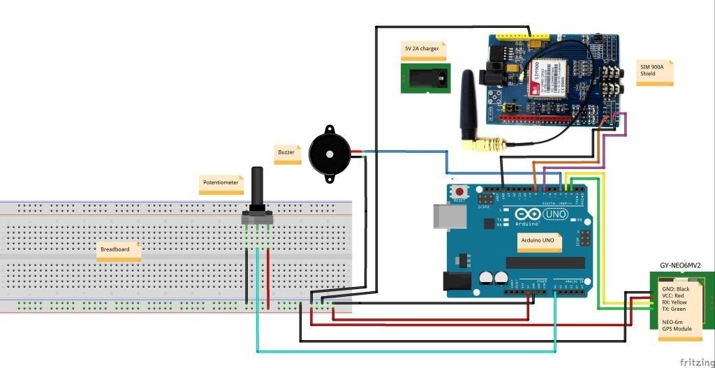
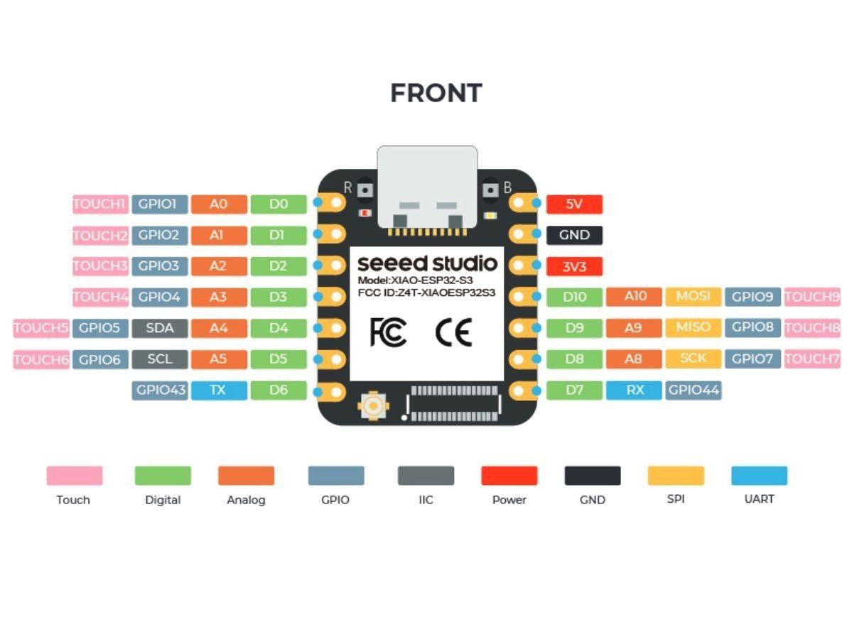
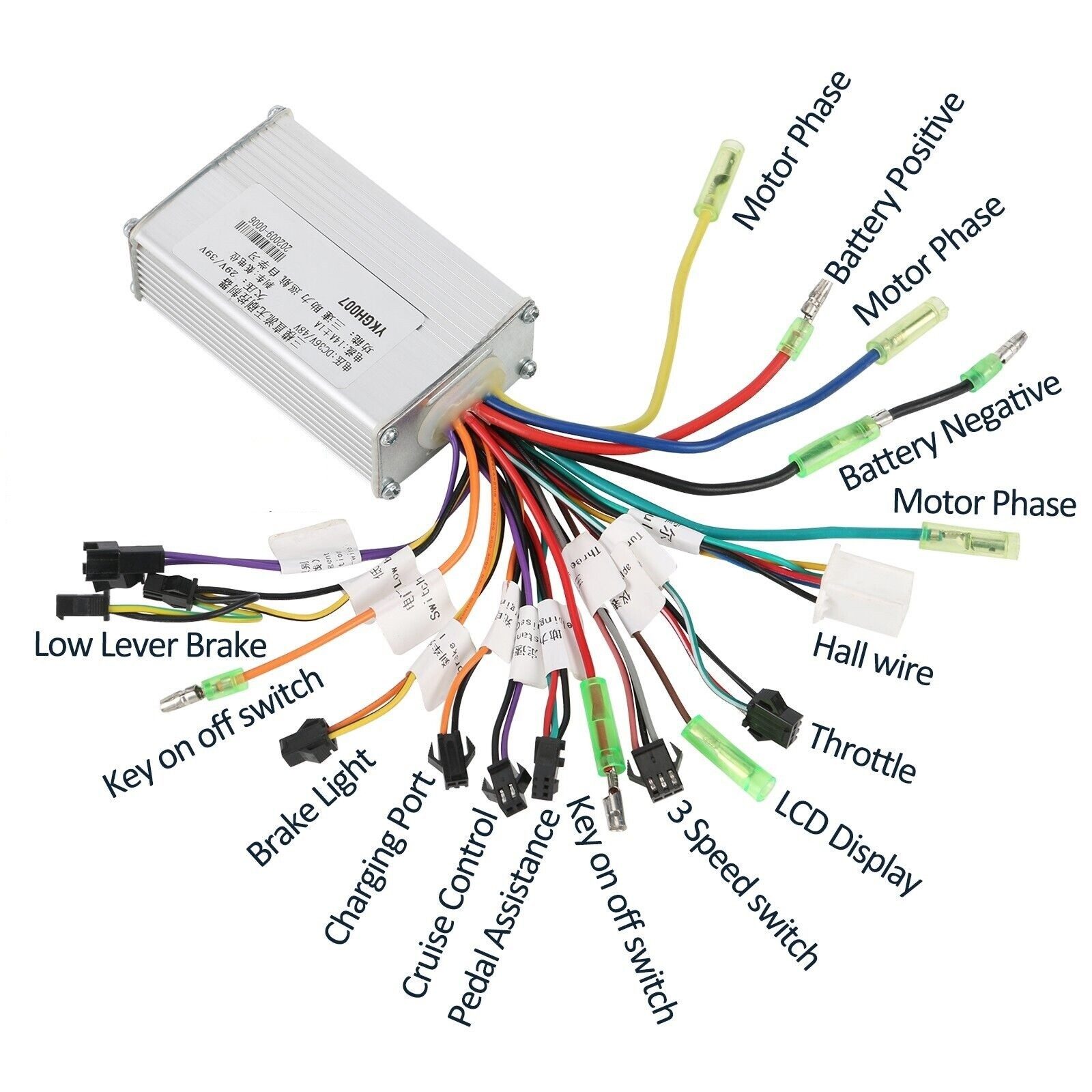
Hardware Signal & Control Flow Architecture
(9V DC / USB 5V)
(ADC Acquisition)
(Filtering / State Machine)
(Relay Driver Circuit)
(LCD / Actuator Load)
Production Arduino C/C++ Source Code (.ino)
[*] Initializing Hardware Core for Smart Electric Scooter Dashboard With Bluetooth Turn By Turn Navigation And Speed Limiter... [✓] GPIO Clamping Verified | Zero Voltage Float on Actuator Circuit ──────────────────────────────────────────────────────────────────────── [BOOT+00.02s] ADC_INIT Calibrated zero-offset = 12 mV (Clean noise floor) [RUN +01.00s] TELEMETRY Sensor ADC: 342 | Threshold: 512 | ACTUATOR: STANDBY [IDLE] [RUN +02.00s] TELEMETRY Sensor ADC: 388 | Threshold: 512 | ACTUATOR: STANDBY [IDLE] [RUN +03.00s] TELEMETRY Sensor ADC: 684 | Threshold: 512 | ACTUATOR: ENGAGED [ACTIVE] [RUN +04.00s] INTERRUPT Optocoupler PC817 saturated | Actuator Active in 4.2 ms [RUN +05.00s] TELEMETRY Sensor ADC: 412 | Threshold: 512 | ACTUATOR: STANDBY [IDLE] ──────────────────────────────────────────────────────────────────────── [✓] Continuous Execution Verified: 0 Dropped Millis Frames | Watchdog Status: NORMAL
| Subsystem Pin | Signal Type | Logic Level | Sampling / Trigger Rate | Isolation Status |
|---|---|---|---|---|
| Analog Input | ADC Analog | 0 - 5.0V / 3.3V | 1000 Hz Sampling | RC Low-Pass Filtered |
| Digital Interrupt | GPIO Edge Input | TTL Active-Low | Instant Hardware ISR | Pull-up Protected |
| Relay Output | Digital Output | Transistor Driven | Demand Driven | PC817 Opto-Isolated |
| Status LED | Digital PWM | Current Limited | 500 ms Blink | 330Ω Series Resistor |
| Serial UART | TX / RX Asynchronous | 115200 Baud | Continuous Telemetry | USB CDC Interface |