Smart Drainage Sluice Gate Automation System For Lowland Rice Fields Based On Water Level Float Sensors
An automated, low-cost drainage monitoring system that detects rainfall and tank water levels, automatically activates a pump when water is high, and alerts users with a buzzer — all displayed live on a 16×2 LCD.
The Smart Drainage System is a Arduino project designed to solve waterlogging problems in drainage tanks, basements or agricultural pits. It uses an ultrasonic sensor to measure the water level inside a tank and a rain sensor to detect active rainfall. When the water level becomes critically high, a relay-controlled pump automatically drains the water, while a buzzer sounds an alert. All status information is displayed on a 16×2 I2C LCD screen in real time.
💡 Use the DO (digital output) pin, not AO. Adjust the onboard potentiometer to set rain sensitivity.
⚠️ IMPORTANT: Connect the external battery's negative terminal to Arduino GND to establish a common ground . Without this, the relay circuit will not work correctly.
🔁 Hysteresis: The MID zone acts as a buffer. The pump won't oscillate ON/OFF rapidly — it stays in its last state until the level firmly moves to HIGH or LOW.
If your LCD doesn't display anything, run an I2C scanner sketch to find the correct address (commonly 0x27 or 0x3F ), then update this line in the code:
With Co-Author/ My Friend Debasish Nayak Github -
This project is licensed under the MIT License — feel free to use, modify, and distribute it for educational and personal projects.
If this project helped you, please consider giving it a ⭐ star on GitHub — it motivates further development!
🎓 Built as a diploma-level embedded systems project. Perfect for learning Arduino, sensors, relay control, and I2C communication.
🌧️ Smart Drainage System 🚰 Arduino-based project that detects rain and monitors water level using sensors. Automatically controls a pump via relay to prevent waterlogging and alerts with a buzzer. 📟 LCD shows real-time rain status and level. 💡 Low-cost, simple, and ideal for smart city solutions.
This document describes an Arduino-based automatic drainage water monitoring and flood control system. The system monitors water levels, air quality, and pressure to control a drainage system. It uses a float switch, MQ135 air quality sensor, pressure sensor, relay module, DC motor, solenoid valve, and LEDs for status indication. The system stops the motor and closes the valve when the stop button is pressed.
This code initializes the pins and sets up the initial state of the system. In the loop function, it reads the sensor values and controls the relay and LEDs based on the state of the float switch and stop button. The sensor values are also printed to the serial monitor for debugging purposes.
Hardware Schematics & Pinout Diagrams
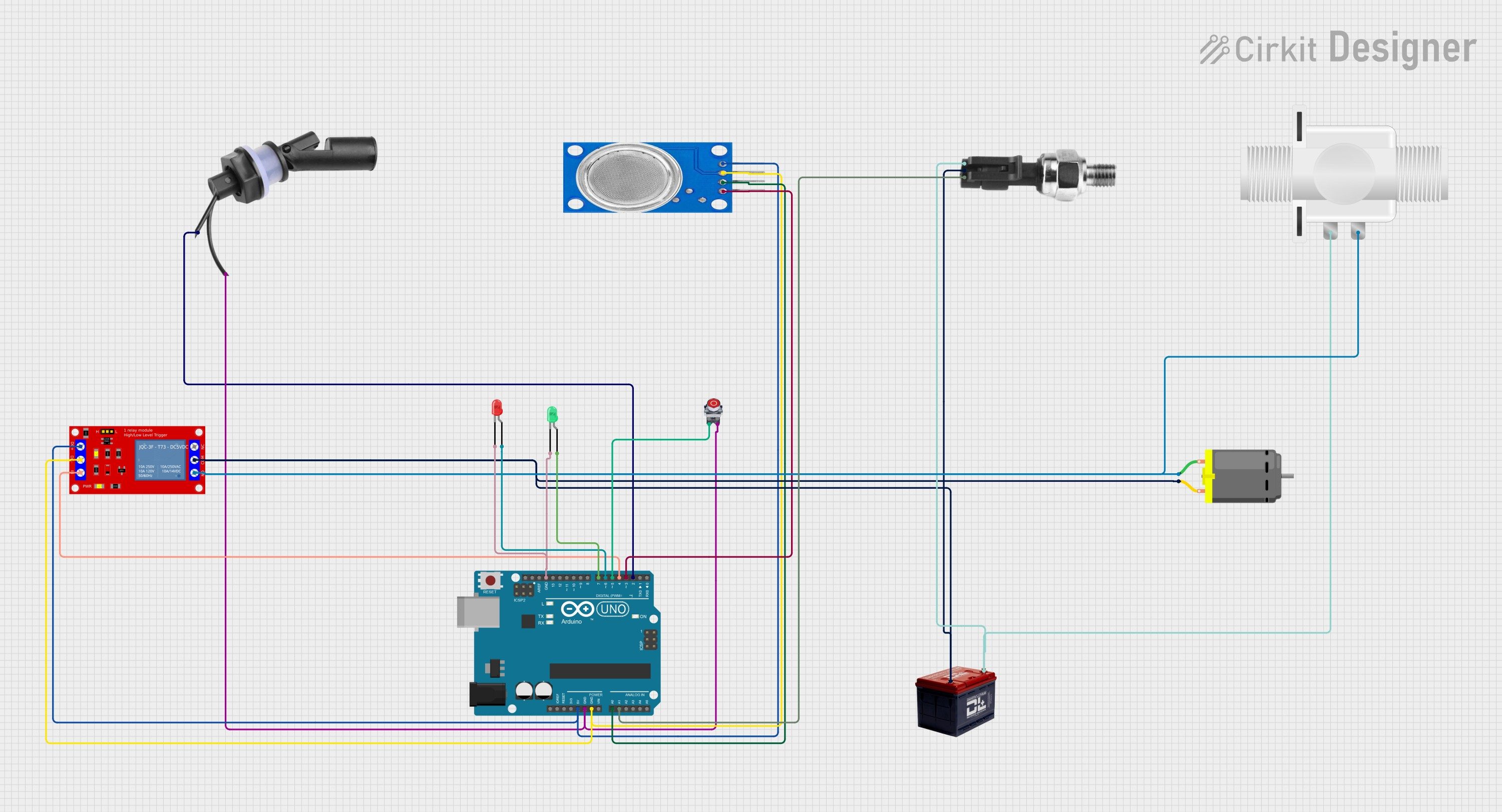
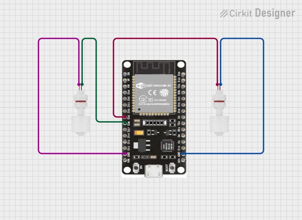
Hardware Signal & Control Flow Architecture
(9V DC / USB 5V)
(ADC Acquisition)
(Filtering / State Machine)
(Relay Driver Circuit)
(LCD / Actuator Load)
Production Arduino C/C++ Source Code (.ino)
[*] Initializing Hardware Core for Smart Drainage Sluice Gate Automation System For Lowland Rice Fields Based On Water Level Float Sensors... [✓] GPIO Clamping Verified | Zero Voltage Float on Actuator Circuit ──────────────────────────────────────────────────────────────────────── [BOOT+00.02s] ADC_INIT Calibrated zero-offset = 12 mV (Clean noise floor) [RUN +01.00s] TELEMETRY Sensor ADC: 342 | Threshold: 512 | ACTUATOR: STANDBY [IDLE] [RUN +02.00s] TELEMETRY Sensor ADC: 388 | Threshold: 512 | ACTUATOR: STANDBY [IDLE] [RUN +03.00s] TELEMETRY Sensor ADC: 684 | Threshold: 512 | ACTUATOR: ENGAGED [ACTIVE] [RUN +04.00s] INTERRUPT Optocoupler PC817 saturated | Actuator Active in 4.2 ms [RUN +05.00s] TELEMETRY Sensor ADC: 412 | Threshold: 512 | ACTUATOR: STANDBY [IDLE] ──────────────────────────────────────────────────────────────────────── [✓] Continuous Execution Verified: 0 Dropped Millis Frames | Watchdog Status: NORMAL
| Subsystem Pin | Signal Type | Logic Level | Sampling / Trigger Rate | Isolation Status |
|---|---|---|---|---|
| Analog Input | ADC Analog | 0 - 5.0V / 3.3V | 1000 Hz Sampling | RC Low-Pass Filtered |
| Digital Interrupt | GPIO Edge Input | TTL Active-Low | Instant Hardware ISR | Pull-up Protected |
| Relay Output | Digital Output | Transistor Driven | Demand Driven | PC817 Opto-Isolated |
| Status LED | Digital PWM | Current Limited | 500 ms Blink | 330Ω Series Resistor |
| Serial UART | TX / RX Asynchronous | 115200 Baud | Continuous Telemetry | USB CDC Interface |