Smart Domestic Compost Tumbler With Moisture
The DIY Smart Composting System is a beginner-friendly STEM project that demonstrates how sensors and a microcontroller can be used to monitor the conditions inside a small composting container. Temperature, moisture and container conditions are measured and displayed so students can understand how composting conditions change over time. The Smart Composting System project combines electronics, programming, environmental science, sensing, data monitoring and practical sustainability in a hands-on classroom activity.
Transforms a simple compost container into a monitored smart-composting model. Instead of checking the compost only by observation, the system continuously reads selected environmental conditions and provides a simple status indication when the compost is too dry, too wet or outside the selected temperature range.
Sensors → Arduino → Condition Analysis → LCD/LED/Buzzer Feedback → Compost Management.
The temperature sensor measures the compost environment while the moisture sensor estimates the moisture condition of the composting material. An optional ultrasonic sensor can estimate how full the container is. The Arduino compares the readings with user-defined ranges and displays a status such as GOOD, TOO DRY, TOO WET or CHECK TEMPERATURE. The indicators provide quick visual or audible feedback.
Step 1: Prepare the Compost Container — Use a small ventilated container or bucket. Add a demonstration mixture of dry leaves or shredded cardboard and suitable organic food scraps.
Step 2: Create Ventilation — Make small air holes in the container or use a ventilated lid. Composting requires airflow, so do not make the container completely airtight.
Step 3: Mount the Temperature Sensor — Place the temperature/humidity sensor where it can measure the surrounding compost environment without being buried in wet material.
Step 4: Install the Moisture Sensor — Insert the capacitive moisture sensor into the compost mixture at a consistent depth. Keep the electronics portion protected from moisture.
Step 5: Add the Optional Fill-Level Sensor — Mount an ultrasonic sensor above the compost if you want the system to estimate how full the container is.
Step 6: Connect the LCD — Connect the 16×2 I2C LCD to the Arduino using the I2C pins. The display will show temperature, moisture and system status.
Step 7: Connect the Indicators — Connect green, yellow and red LEDs through suitable resistors. Add a buzzer if an audible warning is required.
Step 8: Build the Arduino Program — Create a program that reads the sensors at regular intervals and compares the readings with calibrated limits.
Step 9: Calibrate the Moisture Sensor — Record readings from dry and suitably moist compost material. Use these readings to establish approximate dry, acceptable and wet ranges for the demonstration.
Step 10: Set Temperature Conditions — Choose a classroom demonstration range appropriate to the sensor and project. The exact thresholds should be treated as adjustable rather than universal composting limits.
Step 11: Add Decision Logic — If moisture is below the selected range, display TOO DRY. If it is above the selected range, display TOO WET. Otherwise display MOISTURE OK. Add a separate temperature status.
Step 12: Add Alerts — Use the yellow or red LED and buzzer when a condition requires attention. Use the green LED when the readings are within the selected demonstration range.
Step 13: Test the System — Change the moisture condition of the sample carefully and observe the sensor reading, LCD message and indicators.
Step 14: Monitor and Improve — Record readings over several days and compare the changes. Adjust sensor placement, thresholds and sampling intervals as necessary.
The LCD displays the current composting conditions, such as temperature and moisture status. When the moisture reading is within the calibrated demonstration range, the green LED indicates an acceptable condition. If the compost becomes too dry or too wet, the appropriate warning appears on the LCD and the yellow/red indicator or buzzer alerts the user. With the optional ultrasonic sensor, the system can also indicate when the compost container is approaching its selected fill level.
The DIY Smart Composting System connects environmental science with practical STEM learning. Students learn how temperature and moisture conditions can be measured electronically and converted into useful feedback through an Arduino, LCD, LEDs and buzzer. By recording readings and adjusting the system over time, learners can explore sustainable waste management, sensor technology, programming, calibration and engineering design in one practical project.
1. What is the purpose of the DIY Smart Composting System? Smart Composting System demonstrates how an Arduino and sensors can monitor selected composting conditions and provide useful status information through an LCD, LEDs and buzzer.
2. Which sensors are used? The Smart Composting System project uses a temperature/humidity sensor and a capacitive moisture sensor. An ultrasonic sensor can also be added to estimate the compost container’s fill level.
3. Can this DIY Smart Composting System automatically make compost? The basic Smart Composting System project monitors conditions and provides alerts rather than automatically managing the compost. Automatic watering, ventilation or mixing can be added as advanced extensions.
4. Can the moisture threshold be changed? Yes. The threshold can be adjusted after testing the sensor with the actual compost mixture and container. Calibration helps establish suitable demonstration ranges for the particular setup.
5. Can the readings be stored? Yes. An SD-card module or an IoT-based data system can be added to record temperature, moisture and other readings over time.
6. Can our DIY Smart Composting System work outdoors? Yes, provided the electronic components are properly enclosed and protected from rain, condensation and direct moisture exposure.
7. Is this Smart Composting System beginner-friendly? Yes. The basic monitoring version is suitable for students learning Arduino programming, sensors, data interpretation and environmental STEM concepts.
Pick your city, district or county. Each page has local class times, kit shipping notes, and a trial button for families in that place.
Smart-Compost-Bin This project focuses on the use of DHT11 and soil humidity sensor backed by an Arduino board in order to create a smart composting system.
Problem Statement The improper tracking of moisture levels and temperature during decomposition leading to improper formation of compost.
Idea A device that measures and tracks various parameters required for proper decomposition.
Prototypes and rejected versions Click https://drive.google.com/file/d/1NsjOQaT7277Kws2XYOTswzE_B9CkjLqm/view?usp=sharing for pictures. Video Link- https://drive.google.com/file/d/196XE0vtusxOqqEp6j_u0zVQryOqMpwhY/view?usp=sharing
Final Project idea /Solution An ESP based device that checks Compost Moisture and outside temperature,humidity conditions to give recommendations to users using a mobile application.It also turns the compost in order for all of it to be exposed to oxygen and heat which increases the efficiency of the method and completely automates it.
Objectives of the project -Measure moisture and temperature of air -Measure compost moisture -Turn/Churn the compost in the bucket once a day -Check the data with the ideal conditions required for compost -Create the plan of action to compensate the difference -Send the recommendations to a phone using a mobile application.
Block diagram based on objectives Click https://drive.google.com/file/d/1j5rjSOnQol7ovM6j-cI9oslBV150rppe/view?usp=sharing for pictures
List of materials needed 1)Node MCU-ESP8266 Module - Link https://www.amazon.in/Lolin-NodeMCU-ESP8266-CP2102-Wireless/dp/B010O1G1ES/ref=sr_1_4?crid=2I72FWKT93W8Q&keywords=esp8266&qid=1696227403&sprefix=esp8266%2Caps%2C271&sr=8-4#customerReviewshttps://www.amazon.in/Lolin-NodeMCU-ESP8266-CP2102-Wireless/dp/B010O1G1ES/ref=sr_1_4?crid=2I72FWKT93W8Q&keywords=esp8266&qid=1696227403&sprefix=esp8266%2Caps%2C271&sr=8-4#customerReviews
2)DHT11 Sensor Module - Link https://www.amazon.in/Robodo-Electronics-DHT11-Temperature-Raspberry/dp/B00BOMEO5U/ref=sr_1_1?crid=1E1ZJLWPOM2OT&keywords=DHT11&qid=1696227574&sprefix=dht1%2Caps%2C201&sr=8-1
3)Soil Moisture Sensor Module- Link https://www.amazon.in/EVANA-Moisture-Hygrometer-Detection-Multicolour/dp/B01AV14S00/ref=sr_1_5?crid=1CGDGISLJSKEN&keywords=soil+moisture+sensor&qid=1696345892&sprefix=soil+moisture+senso%2Caps%2C272&sr=8-5
4)Female to Female Jumper wires - Link https://www.amazon.in/ApTechDeals-Jumper-Female-breadboard-jumper/dp/B074J9CPV3/ref=sr_1_4?crid=R3EUKIUR46Z2&keywords=female+to+female+jumper+wires&qid=1696227915&sprefix=female+to+female%2Caps%2C200&sr=8-4
5)300 RPM 12 DC Motor- Link https://www.amazon.in/Robodo-Electronics-Johnson-Geared-Robotics/dp/B00N4O7GU6/ref=sr_1_2?crid=186FS0ZSRNZXM&keywords=300+rpm+gear+motor+12v+dc&qid=1696227976&sprefix=300+rpm+dc+motor%2Caps%2C209&sr=8-2
12)5V Relay - Link https://www.amazon.in/Channel-Module-Switch-Isolation-Trigger/dp/B08242LQ68/ref=sr_1_2?crid=35NN9SG128DJ0&keywords=5v+relay&qid=1696231316&sprefix=5v+relay%2Caps%2C195&sr=8-2
Logic of the complete program -The device has one mode; i)Updating information to the user The Operation -The lid is placed on top of the bucket. -The soil moisture sensor immediately sends a message to the user and tells them how much water/dry material the user needs to put in -The air temperature sensor measures the temperature and accordingly tells the user to place the assembly into a cooler or hotter environment. -All of this data is displayed and printed on the blynk app. -After the user has made the necessary changes to the components inside, the user can enable to motor once, using a button in the app itself.
For the assembly use a bucket and a cap or slit the diameter of that bucket to put in the components such as the motor, DHT11 sensor and the soil humidity sensor.
Click https://drive.google.com/file/d/1snu3IY4oP5G4K0erBR5lxHsDfZ9WPsQx/view?usp=sharing for pictures
We didn’t find a lot of bugs while programming as the code is very straightforward and simple however it would be good to check that all your components are working accurately before running the master code.
Click https://drive.google.com/file/d/14JdgYnkZ9MLAtqW5SuIytds9uqhCBcYh/view?usp=drive_link
This project focuses on the use of DHT11 and soil humidity sensor backed by an Arduino board in order to create a smart composting system.
An AI-powered smart compost bin that automatically classifies compost maturity stage using low-cost IoT sensors and a trained machine learning model, so users don't need manual lab testing to know when their compost is ready to use.
Composting is a sustainable way to manage organic waste, but most households and small farms struggle to know when compost has actually matured and is safe to use. Judging maturity by smell, color, or texture is unreliable, and proper lab testing (Germination Index, C/N ratio, nutrient content) is accurate but slow and inaccessible for everyday use.
This project combines low-cost sensors with a trained Decision Tree model to automatically classify compost into one of four stages — Not Ready → Thermophilic → Cooling → Mature — and responds with automated outputs (display, alert, and aeration) based on the detected stage.
Hardware Schematics & Pinout Diagrams
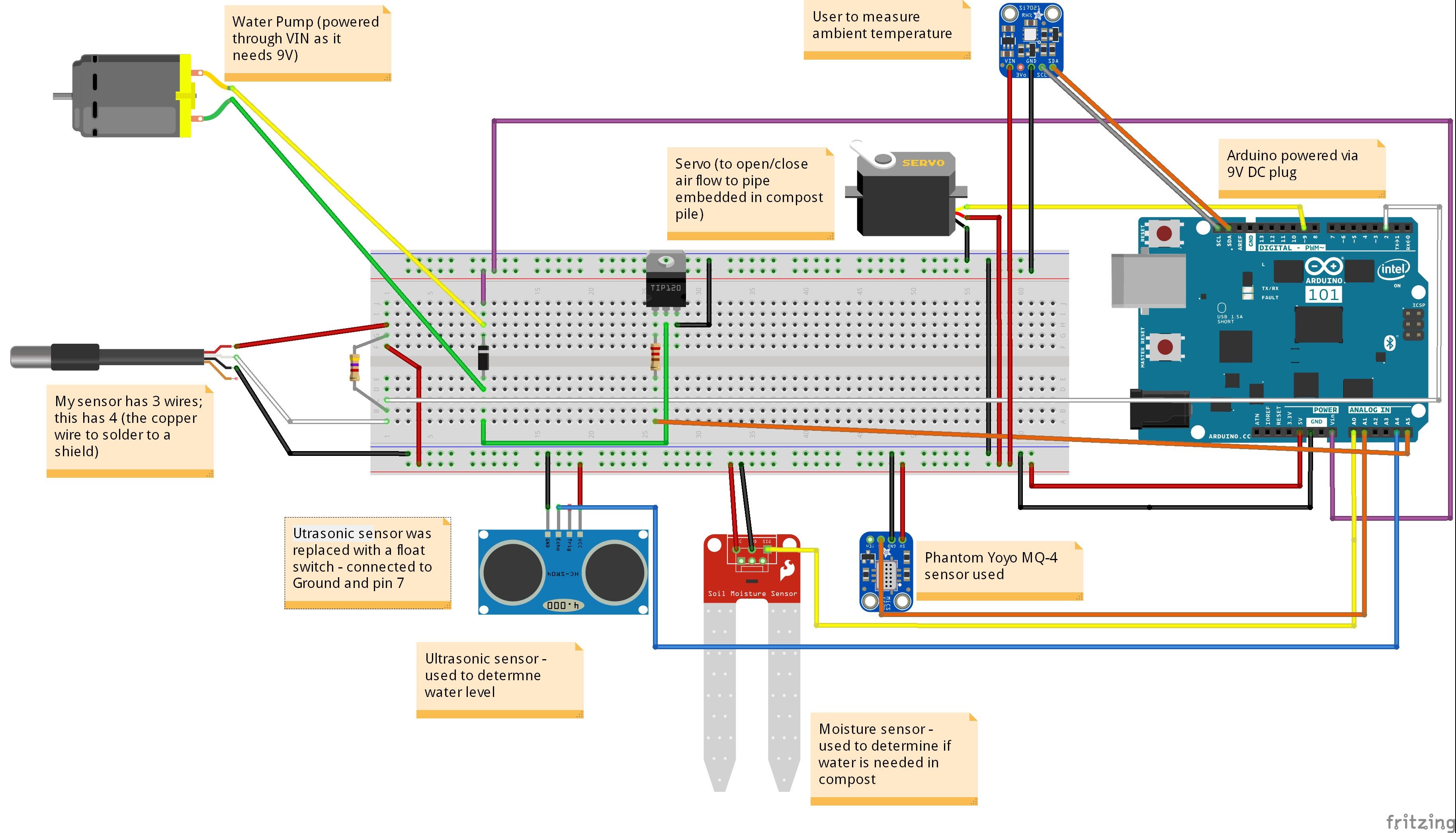
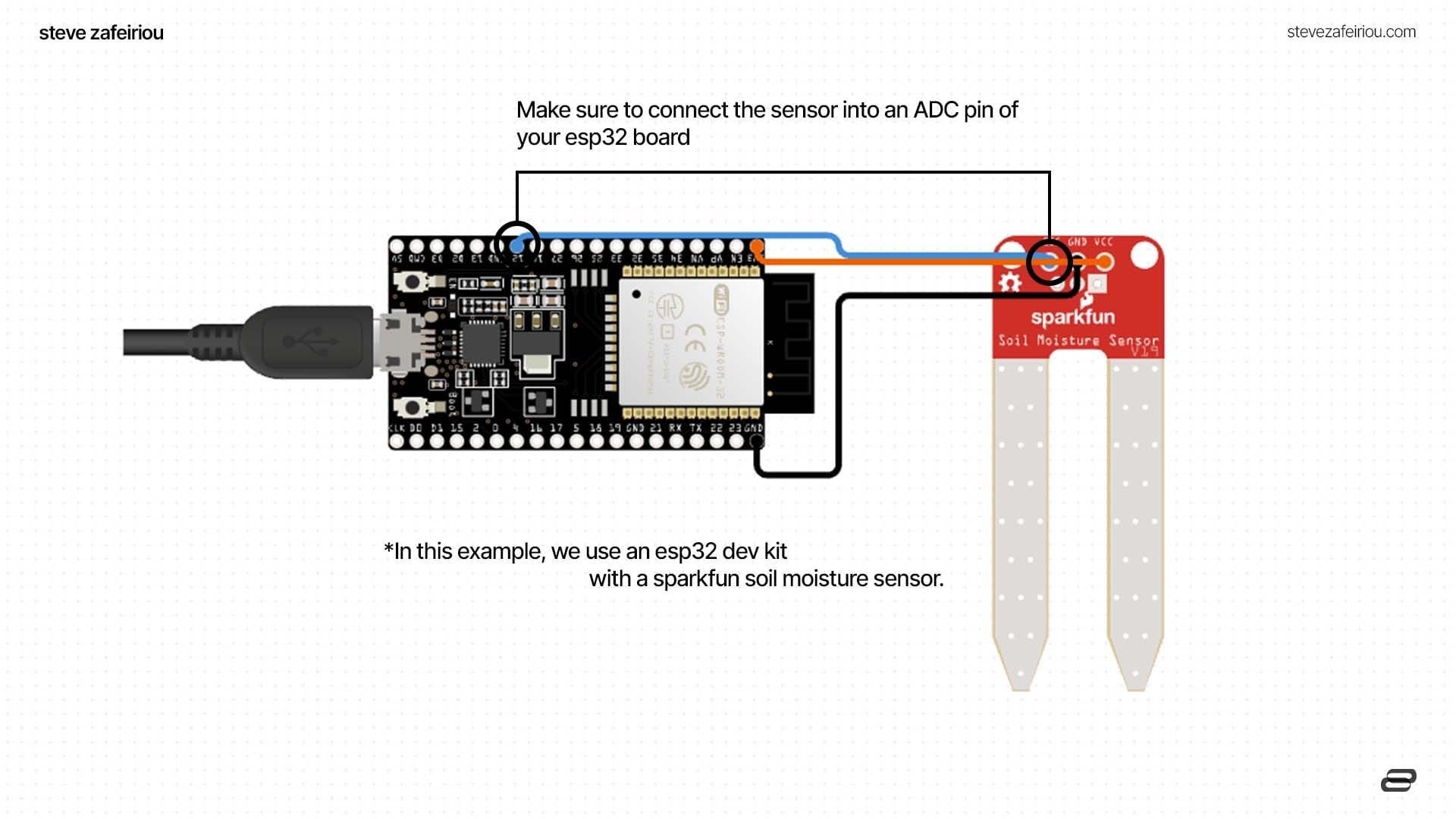
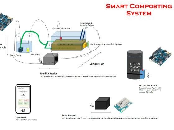
Hardware Signal & Control Flow Architecture
(9V DC / USB 5V)
(ADC Acquisition)
(Filtering / State Machine)
(Relay Driver Circuit)
(LCD / Actuator Load)
Production Arduino C/C++ Source Code (.ino)
[*] Initializing Hardware Core for Smart Domestic Compost Tumbler With Moisture... [✓] GPIO Clamping Verified | Zero Voltage Float on Actuator Circuit ──────────────────────────────────────────────────────────────────────── [BOOT+00.02s] ADC_INIT Calibrated zero-offset = 12 mV (Clean noise floor) [RUN +01.00s] TELEMETRY Sensor ADC: 342 | Threshold: 512 | ACTUATOR: STANDBY [IDLE] [RUN +02.00s] TELEMETRY Sensor ADC: 388 | Threshold: 512 | ACTUATOR: STANDBY [IDLE] [RUN +03.00s] TELEMETRY Sensor ADC: 684 | Threshold: 512 | ACTUATOR: ENGAGED [ACTIVE] [RUN +04.00s] INTERRUPT Optocoupler PC817 saturated | Actuator Active in 4.2 ms [RUN +05.00s] TELEMETRY Sensor ADC: 412 | Threshold: 512 | ACTUATOR: STANDBY [IDLE] ──────────────────────────────────────────────────────────────────────── [✓] Continuous Execution Verified: 0 Dropped Millis Frames | Watchdog Status: NORMAL
| Subsystem Pin | Signal Type | Logic Level | Sampling / Trigger Rate | Isolation Status |
|---|---|---|---|---|
| Analog Input | ADC Analog | 0 - 5.0V / 3.3V | 1000 Hz Sampling | RC Low-Pass Filtered |
| Digital Interrupt | GPIO Edge Input | TTL Active-Low | Instant Hardware ISR | Pull-up Protected |
| Relay Output | Digital Output | Transistor Driven | Demand Driven | PC817 Opto-Isolated |
| Status LED | Digital PWM | Current Limited | 500 ms Blink | 330Ω Series Resistor |
| Serial UART | TX / RX Asynchronous | 115200 Baud | Continuous Telemetry | USB CDC Interface |