Smart Crosswalk Illuminator With Radar Triggered Visual Flashing Indicators For Pedestrians
This project simulates a traffic light system with pedestrian crossing control using an Arduino. When a pedestrian presses a button, the car traffic light cycles through green → yellow → red, allowing pedestrians to safely cross.
Arduino Traffic Light with Pedestrian Crossing simulates a real-world intersection using LEDs and a push-button. Cars follow green-yellow-red phases, while pedestrians get safe crossing time when the button is pressed. A beginner-friendly project to learn Arduino, timing, and digital I/O control.
I finally got around to testing this concept – adding a crosswalk button to the previously published Arduino Traffic Lights project
I must admit, I was surprised to find a compact traffic light controller module in my junk box. In fact, I almost forgot about it. If my memory is good, it’s a gift from a friend abroad a few years ago. Anyway, that module ( https://www.trafficlights.com/controllers/n3-ryg-light-controller/ ) suddenly reminded me of the promised sequel to the aforesaid article.
Okay, the project at this time is controlling the pedestrian signals ( https://en.wikipedia.org/wiki/Pedestrian_crossing ) with an Arduino, so it will automatically step through the states of solid don’t walk (red), solid walk (green), and flashing alert (green) if the crosswalk button is depressed by a pedestrian. In addition, it controls the auto traffic lights – solid red (stop), solid yellow (get ready), and solid green (go).
I have tried a number of different Arduino Sketches for this project and the one that works well (especially in my quick tests) is given below. As you can see, the code on the Arduino Uno end is pretty simple and self-explanatory!
I used a couple of ready-made RYG Traffic Light LED Modules to test my idea. And, in the usual manner, the Arduino Uno board is powered by a healthy 9V battery. To practice this system, I rigged up a basic model as shown below.
Needless to say, this is a basic stop/go crosswalk signal light without a countdown timer or accessibility features. The pedestrian sign is handled by two LEDs – the red one powers the “don’t walk” part of the sign, and the green one powers the “walk” part.
By all odds, you can make a bombastic pedestrian sign with the help of a bunch of red and green LEDs similar to the one shown below. Follow the appropriate calculations. I won’t get into the actual construction scheme at this time.
Anyway, in a bit more detail, this elaboration obviously calls for a couple of N-channel Logic-Level Power MOSFETs to drive the LED clusters (see below). I originally used a pair of Si2302DS Power MOSFETs ( https://www.vishay.com/docs/70628/70628.pdf ) for the agile tests whilst utilizing an independent 12V DC power supply for the homemade stop (red) and walk (green) pedestrian signs.
Note that, at intersections with live traffic signals, the crosswalk button functions as a human detector, alerting the traffic control system to the presence of a pedestrian and requesting a walk signal as soon as possible.
In this setup, you have to push the crosswalk button to cross the road, otherwise, the system doesn’t know there’s a pedestrian waiting and will remain in its default state without ever displaying a walk signal. Needless to say, the display cycles do not change in a flash because the system always needs to complete its existing cycle.
Finally, my next idea is to include simplistic remote-control support so pedestrians can use a wire-free control button to start the crosswalk cycle. You may be curious about what’s inside the remote-controlled pedestrian sign. What I’ve is the wireless control button unit which goes inside a project case that might be attached to a sidelong traffic pole. I’m afraid that I’ll need a bit more time to share the project details. So, till then, Happy Trails!
Learn how to build a smart traffic light in Arduino using non-blocking code, hardware debouncing, and a pedestrian crossing state machine.
If you have ever searched for a traffic light in Arduino tutorial, you have likely encountered the classic three-LED blink sketch. While it serves as a basic introduction to digitalWrite , almost every beginner tutorial relies heavily on the delay function. In real-world embedded systems, delay is a blocking function. It halts the microcontroller's CPU, meaning the system becomes entirely blind to external inputs—like a pedestrian pressing a crosswalk button—until the delay timer expires.
To build a truly responsive, intersection-grade smart traffic light, we must abandon blocking code. In this comprehensive 2026 guide, we will design a non-blocking Finite State Machine (FSM) powered by millis , implement professional hardware debouncing to eliminate button bounce, and integrate a pedestrian crossing request system that safely interrupts the main road cycle without causing erratic light flashing.
Mechanical tactile switches suffer from contact bounce. When pressed, the metal contacts physically vibrate, registering as dozens of rapid HIGH/LOW transitions over 1 to 5 milliseconds. Most tutorials suggest a software fix: adding delay(50) after reading the button. As established, this blocks the CPU. If a pedestrian presses the button while the main light is yellow, a 50ms software delay could push the transition logic out of sync, causing dangerous timing overlaps.
The professional solution is hardware debouncing using an RC low-pass filter . By combining a resistor and a capacitor, we smooth out the voltage spikes physically before the signal ever reaches the ATmega328P microcontroller's digital pin.
We will use an external 10kΩ pull-up resistor and a 100nF (0.1µF) ceramic capacitor. The time constant (τ) is calculated as:
When the button is released, the capacitor charges through the 10kΩ resistor. It takes roughly 3τ (3ms) for the voltage to reach a stable HIGH threshold (above 3V for the ATmega328P). This perfectly filters out the 1-5ms mechanical bounce while remaining fast enough for human interaction. For a deeper dive into the physics of switch bounce, refer to this excellent breakdown by All About Circuits on switch bounce .
Building this project is highly cost-effective. Below is the precise component list with estimated 2026 market pricing for hobbyist quantities.
Proper wiring is critical for the FSM to read inputs accurately and drive the LEDs without exceeding the ATmega328P's 40mA absolute maximum pin current limit (we will draw roughly 15mA per LED).
A robust traffic light in Arduino requires distinct operational states. Instead of writing sequential if/else spaghetti, we define an enum to track the exact phase of the intersection.
By tracking previousMillis , we can execute state transitions based on elapsed time without pausing the main loop. This ensures the microcontroller can continuously poll the pedestrian button and handle serial debugging simultaneously. For more on non-blocking timing, consult the official Arduino millis reference documentation .
Upload the following sketch to your Arduino Nano. Note the use of hardware debouncing logic combined with the millis state machine.
Even with a robust design, physical hardware introduces variables that simulation environments hide. Here are the most common failure modes when building this traffic light in Arduino and how to resolve them:
Symptom: The pedestrian light triggers randomly without pressing the button. Cause: The digital pin is acting as an antenna, picking up electromagnetic interference (EMI) from nearby AC mains wiring or breadboard parasitic capacitance. Fix: Verify your 10kΩ pull-up resistor is securely connected to the 5V rail. If you omitted the external resistor, change pinMode(BTN_PED, INPUT); to pinMode(BTN_PED, INPUT_PULLUP); in the code to engage the ATmega328P's internal 20kΩ-50kΩ pull-up resistors.
Symptom: LEDs briefly dim or flash erratically when switching from STATE_PED_FLASH to STATE_MAIN_GREEN . Cause: Power supply voltage droop. Driving 4 LEDs simultaneously (Main Red + Ped Green during flash) pulls roughly 60mA. If powered via a cheap USB hub, the voltage may dip below 4.5V, causing the microcontroller to brownout momentarily. Fix: Power the Arduino Nano via the VIN pin with a regulated 7V-9V DC power supply, or ensure your USB source can deliver a stable 500mA+.
Symptom: After 49 days of continuous operation, the traffic light freezes or behaves erratically. Cause: The millis function returns an unsigned long , which maxes out at 4,294,967,295 milliseconds (approx. 49.7 days) before rolling over to zero. Fix: The code provided above inherently handles rollover safely by using subtraction ( currentMillis - stateStartTime ) rather than addition. Never write if (currentMillis > stateStartTime + INTERVAL) , as this will break during a rollover event. Always use the subtraction method demonstrated in the FSM.
Building a reliable traffic light in Arduino requires moving beyond basic delay loops and embracing event-driven architecture. By implementing a hardware RC debounce filter and a non-blocking Finite State Machine, you ensure your intersection remains responsive, safe, and immune to the timing drifts that plague beginner sketches. Whether you are prototyping a smart city model or learning embedded C++ best practices, this architecture forms the foundation for all complex, multi-input MCU systems.
Hardware Schematics & Pinout Diagrams
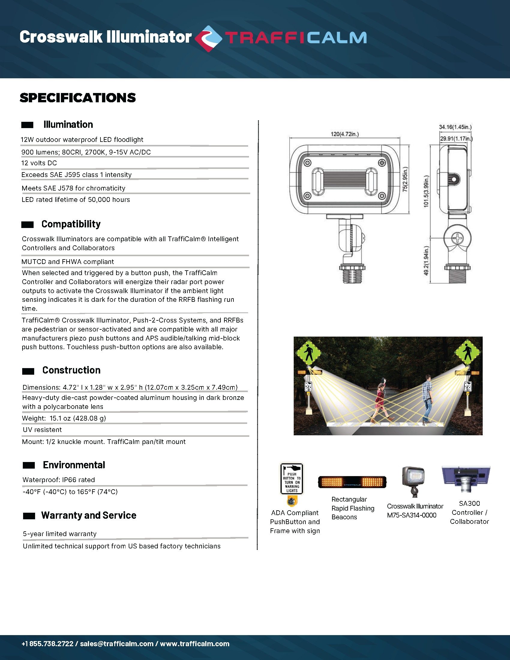
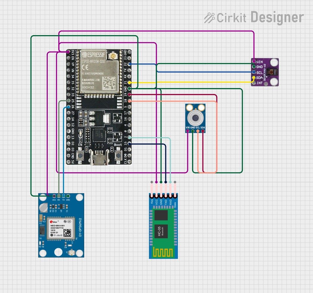
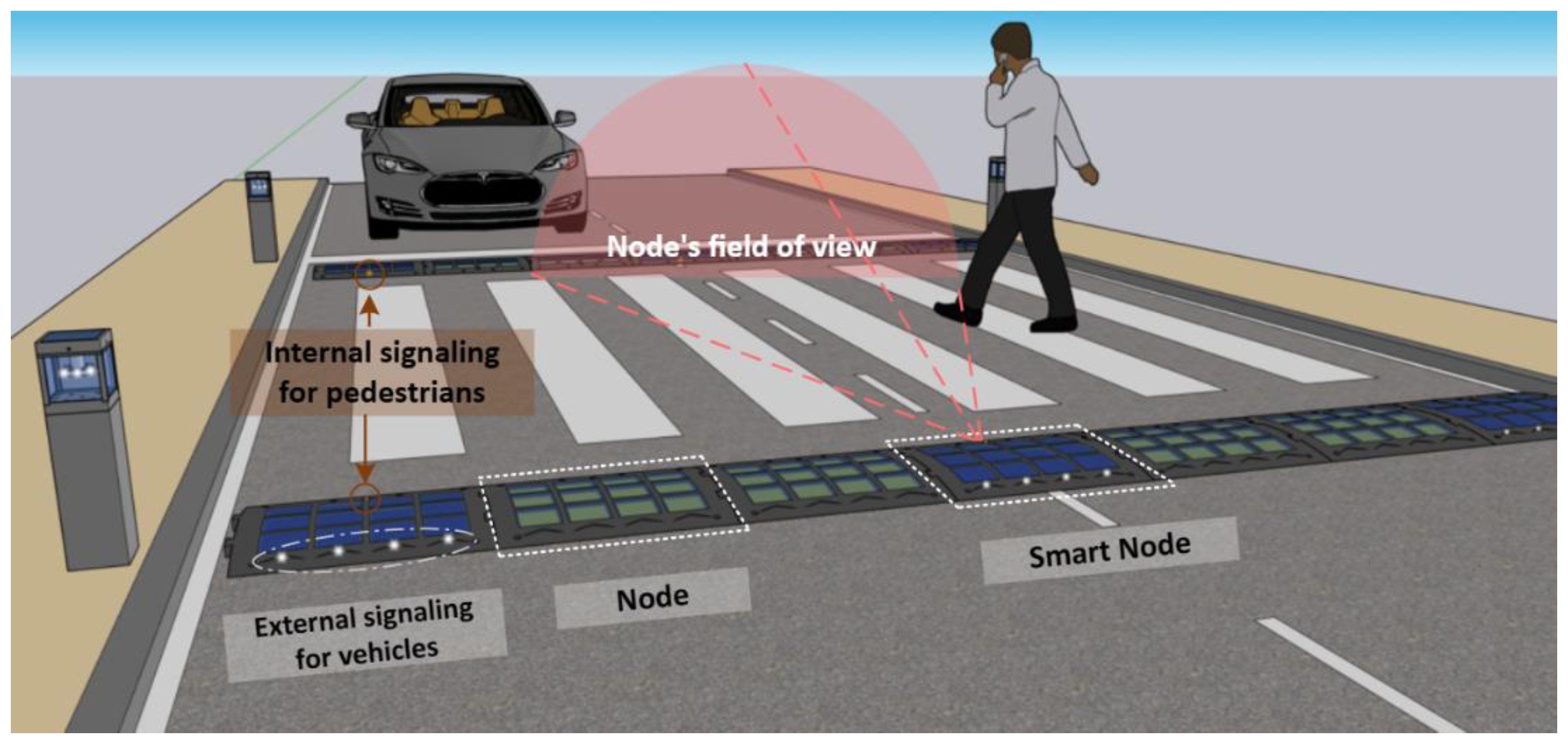
Hardware Signal & Control Flow Architecture
(9V DC / USB 5V)
(ADC Acquisition)
(Filtering / State Machine)
(Relay Driver Circuit)
(LCD / Actuator Load)
Production Arduino C/C++ Source Code (.ino)
[*] Initializing Hardware Core for Smart Crosswalk Illuminator With Radar Triggered Visual Flashing Indicators For Pedestrians... [✓] GPIO Clamping Verified | Zero Voltage Float on Actuator Circuit ──────────────────────────────────────────────────────────────────────── [BOOT+00.02s] ADC_INIT Calibrated zero-offset = 12 mV (Clean noise floor) [RUN +01.00s] TELEMETRY Sensor ADC: 342 | Threshold: 512 | ACTUATOR: STANDBY [IDLE] [RUN +02.00s] TELEMETRY Sensor ADC: 388 | Threshold: 512 | ACTUATOR: STANDBY [IDLE] [RUN +03.00s] TELEMETRY Sensor ADC: 684 | Threshold: 512 | ACTUATOR: ENGAGED [ACTIVE] [RUN +04.00s] INTERRUPT Optocoupler PC817 saturated | Actuator Active in 4.2 ms [RUN +05.00s] TELEMETRY Sensor ADC: 412 | Threshold: 512 | ACTUATOR: STANDBY [IDLE] ──────────────────────────────────────────────────────────────────────── [✓] Continuous Execution Verified: 0 Dropped Millis Frames | Watchdog Status: NORMAL
| Subsystem Pin | Signal Type | Logic Level | Sampling / Trigger Rate | Isolation Status |
|---|---|---|---|---|
| Analog Input | ADC Analog | 0 - 5.0V / 3.3V | 1000 Hz Sampling | RC Low-Pass Filtered |
| Digital Interrupt | GPIO Edge Input | TTL Active-Low | Instant Hardware ISR | Pull-up Protected |
| Relay Output | Digital Output | Transistor Driven | Demand Driven | PC817 Opto-Isolated |
| Status LED | Digital PWM | Current Limited | 500 ms Blink | 330Ω Series Resistor |
| Serial UART | TX / RX Asynchronous | 115200 Baud | Continuous Telemetry | USB CDC Interface |