Small Scale Vertical Axis Wind Turbine Vawt Dump Load Regulator Using Arduino PWM Control
A Vertical Axis Wind Turbine (VAWT) installed between highways to harness wind energy generated by passing vehicles. This Arduino-based system includes real-time voltage/current sensing and an MPPT (Maximum Power Point Tracking) algorithm with a boost converter for stable output.
Wind from passing highway vehicles spins the VAWT. The turbine generates variable DC voltage which is fed into a boost converter. An Arduino UNO continuously monitors the turbine voltage, current, and boost output, then adjusts the PWM duty cycle using an MPPT algorithm to extract maximum power at all times.
The ACS712 offset is auto-calibrated at startup by averaging 500 ADC readings — no manual zero adjustment needed.
This article provides the Arduino source code and usage instructions for the Magnus effect vertical axis wind turbine experimental device. Combined with the previously disclosed circuit diagram, mechanical parts list, and 3D printing STL file , this interesting experiment can be easily implemented. Anyone who is interested can download it and enjoy it ! The dynamic demonstration of this experimental device is shown in the following video:
This article provides 3D printing .STL files, documentation and pictures of the Darrieus wind turbine experimental device, etc. Those who are interested can download it and actually make it to play with! The Darrieus wind turbine is a lift-type vertical axis wind turbine with high rotation speed and high efficiency. It is a subject worth studying. The experimental equipment of this project is shown in the video below :
This article provides the project files of the Magnus effect vertical axis wind turbine experimental device, including 3D printed (STL) files, mechanical parts list, circuit diagram, etc. Anyone who is interested in making one can download it and try it out ! The device of this project is shown in the video :
Since the Magnus effect was described in 1852, it is natural to try to drive wind turbines with it. As for the horizontal axis wind turbine, its structure is not difficult to understand as shown in the figure below. However, if it is implemented as a vertical axis wind turbine, the rotation directions of the cylindrical rotor on the windward side and the leeward side must be opposite, so that the torques will not cancel each other out, so as to drive the wind turbine. In the early days, it could only be made by means of gears and connecting rods, which was difficult to achieve because the structure was too bulky. In recent years, thanks to the rapid advancement of semiconductor technology, microcontroller and motor drive technology has matured, it is no longer difficult to realize this concept. The following video shows this original concept in the real world …
According to the literature, the Darrieus vertical axis wind turbine characterized by high efficiency but it is difficult to be self-starting. I couldn’t understand when I first came into contact with it. Since high efficiency means that it has torque, why can’t it start by itself? Later I realized that its efficiency must appear at a higher speed (similar to the high gear of a car), As for how high the speed should be? Usually 2~6 times faster than wind speed. This puzzles me even more, because the wind turbine is driven by the wind, why can it revolve faster than the wind speed? It seems that an experiment must be done, seeing is believing …
Due to the need for environmental protection and the fight against global warming, the development of renewable energy is urgent. In addition to solar energy, wind energy has attracted the most attention. In order to use wind energy, mankind has invented Wind Turbine for centuries. The wind turbine can convert wind energy into the rotating mechanical energy, and the torque generated by its main shaft can be used to drive a load, such as a generator or a water pump, for power generation or irrigation. According to the direction of the rotation axis, wind turbines can be divided into two types: horizontal axis and vertical axis.
Arduino source code of this project => iCloud Other resources for this project => circuit diagram, mechanical parts,STL file Listed below are the command codes that can communicate through the Arduino serial port to control the behavior of this program. Case insensitive ,( * ) is default value. Code Fuction Format/Description M Message On/Off M0:Message off M1:Message on ( * ) T Test mode T0:Normal operation ( * ), Outputs a sinusoidal command to each motor based on the phase angle. T1:
Hardware Schematics & Pinout Diagrams
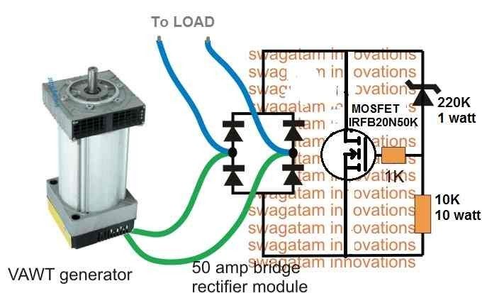
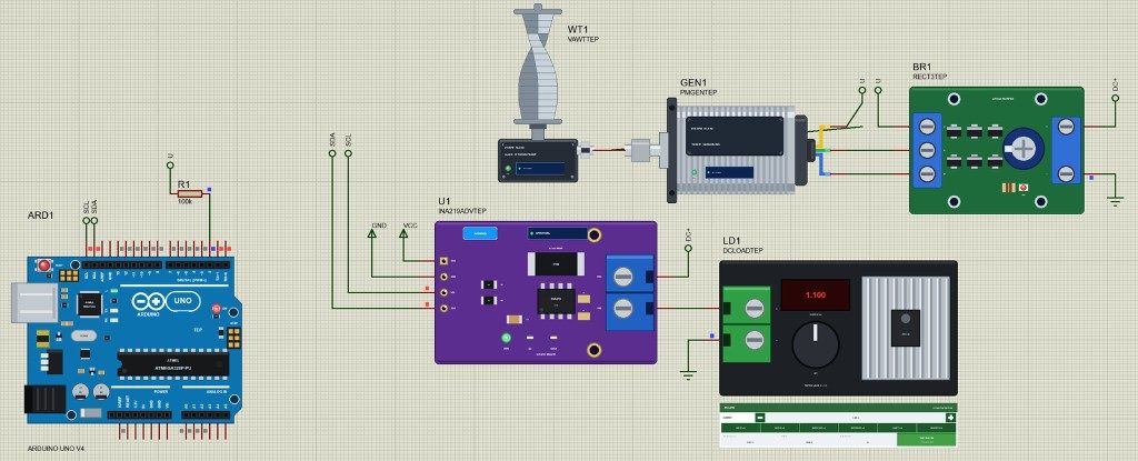
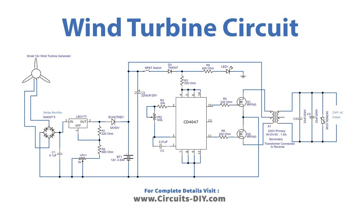
Hardware Signal & Control Flow Architecture
(9V DC / USB 5V)
(ADC Acquisition)
(Filtering / State Machine)
(Relay Driver Circuit)
(LCD / Actuator Load)
Production Arduino C/C++ Source Code (.ino)
[*] Initializing Hardware Core for Small Scale Vertical Axis Wind Turbine Vawt Dump Load Regulator Using Arduino PWM Control... [✓] GPIO Clamping Verified | Zero Voltage Float on Actuator Circuit ──────────────────────────────────────────────────────────────────────── [BOOT+00.02s] ADC_INIT Calibrated zero-offset = 12 mV (Clean noise floor) [RUN +01.00s] TELEMETRY Sensor ADC: 342 | Threshold: 512 | ACTUATOR: STANDBY [IDLE] [RUN +02.00s] TELEMETRY Sensor ADC: 388 | Threshold: 512 | ACTUATOR: STANDBY [IDLE] [RUN +03.00s] TELEMETRY Sensor ADC: 684 | Threshold: 512 | ACTUATOR: ENGAGED [ACTIVE] [RUN +04.00s] INTERRUPT Optocoupler PC817 saturated | Actuator Active in 4.2 ms [RUN +05.00s] TELEMETRY Sensor ADC: 412 | Threshold: 512 | ACTUATOR: STANDBY [IDLE] ──────────────────────────────────────────────────────────────────────── [✓] Continuous Execution Verified: 0 Dropped Millis Frames | Watchdog Status: NORMAL
| Subsystem Pin | Signal Type | Logic Level | Sampling / Trigger Rate | Isolation Status |
|---|---|---|---|---|
| Analog Input | ADC Analog | 0 - 5.0V / 3.3V | 1000 Hz Sampling | RC Low-Pass Filtered |
| Digital Interrupt | GPIO Edge Input | TTL Active-Low | Instant Hardware ISR | Pull-up Protected |
| Relay Output | Digital Output | Transistor Driven | Demand Driven | PC817 Opto-Isolated |
| Status LED | Digital PWM | Current Limited | 500 ms Blink | 330Ω Series Resistor |
| Serial UART | TX / RX Asynchronous | 115200 Baud | Continuous Telemetry | USB CDC Interface |