Single Phase Inverter Output Voltage Stabilization Under Abrupt Load Steps Using Arduino
Single phase sine wave inverter using Arduino: I hope all of you are fine and doing well. In today’s project , I am going to talk about our newly design project on arduino based pure sine wave inverter using sinusoidal pulse width modulation technique. I have already written a article on three phase sine wave inverter using arduino . So there are many people who are asking me to make a project on single phase sine wave inverter using Arduino also. I have made a proteus simulation and written a code in Arduino IDE . In this project, I have used Arduino Uno R3 for to generate PWM signals to drive MOSFET driver 1R2110 . I will explain it in more detail in later part of this article. This inverter can convert 12 volt DC voltage to 220 volt AC volt with frequency of 50HZ and 60HzZ. User can select either 50Hz or 60 Hz according to their requirement. H bridge topology is used to convert dc voltage into ac voltage. Step up transformer is used to step up output of H bridge to 220V AC. After step up transformer, a LC filter is used to get pure sine wave from pulsating output wave.
Followings are the main components used in single phase pure sine wave inverter using arduino. I provided a brief explanation of each component below:
Circuit diagram of single phase pure sine wave inverter using arduino is given below. I think all the component used in this project are self explanatory or I have explained them above.
Hello Bilal, My name is Alex, and one part of my project is to use Arduino and single phase H bridge inverter to get the DC-AC transfer, so could you please show me your arduino code, it is really helpful to me. Thanks a lot. Kind regards
Hi Alex code is not free of cost. you can purchase code from here http://store.microcontrollerslab.com/product/arduino-based-single-phase-sine-wave-inverter-code-and-proteus-simulation/
Dear Sir, Can I send the details of my project to you, since I want to double check whether I can use that, thanks for your help.
YES send your project details on this email ID : microcontrollerslabhub@gmail.com
Nicely written article, I wish it was for free, but I have 3 question. . Can the pins in the arduino be changed to any other to make the SPWM. .The 1m inductor ( or inductance) in the output, does it have a core or how do I make the core? .What guage of wire should i use.
yes it can be changed but it should be PWM pins only and size of wire depends on amount of current
Thank you very much, still don’t understand the output inductance what kind of core do you recommend?
plse sir how do i calculate my lc filter to obtain a sine wave.i have written the code but i having problem with lc filtering calculation
one part of my project is to use Arduino to generate spwm so could you please show me your arduino code and which software you are using for that
please sir, does this arduino code have a PID or any form of feedback control function? im interested in this project
This article explains a simple pure sine wave inverter circuit using Arduino , which could be upgraded to achieve any desired power output as per the user's preference.
In the last article I have explained how to generate sine wave pulse width modulation or SPWM though Arduino , we are going to use the same Arduino board to make the proposed simple pure sine wave inverter circuit. The design is actually extremely straightforward, as shown in the following figure.
You just have to program the arduino board with the SPWM code as explained in the previous article, and hook it up with some of the external devices.
Pin#8 and pin#9 generate the SPWMs alternately and switch the relevant mosfets with the same SPWM pattern.
The mosfst in turn induce the transformer with high current SPWM waveform using the battery power, causing the secondary of the trafo to generate an identical waveform but at the mains AC level .
The proposed Arduino inverter circuit could be upgraded to any preferred higher wattage level, simply by upgrading the mosfets and the trafo rating accordingly, alternatively you can also convert this into a full bridge or an H-bridge sine wave inverter
In the diagram the Arduino board could be seen supplied from a 7812 IC circuit, this could be built by wiring a standard 7812 IC in the following manner. The IC will ensure that the input to the Arduino never exceeds the 12V mark, although this might not be absolutely critical, unless the battery is rated over 18V.
If you have any questions regarding the above SPWM inverter circuit using a programmed Arduino, please feel free to ask them through your valuable comments.
Image of SPWM waveform as obtained from the above Arduino inverter design (Tested and Submitted By Mr. Ainsworth Lynch)
Since an Arduino board will produce a 5V output, it may not be an ideal value for driving mosfets directly.
Therefore an intermediate BJT level shifter stage may be required for raising the gate level to 12V so that the mosfets are able to operate correctly without causing unnecessary heating up of the devices,. The updated diagram (recommended) can be witnessed below:
To ensure that the mosfet stages initiate with a delay during the Arduino booting or start up, you may modify left side BC547 transistors into delay ON stages, as shown below. This will safeguard the mosfets and prevent them from burning during power switch ON Arduino booting.
If you are not comfortable with the response of the above passive delay ON timer circuit, you can employ the following configuration using BJTs and a relay . This design is extremely reliable and will effectively protect your Arduino and the inverter from burning due to a malfunctioning delay effect.
Just like any other inverter the output from this design can rise to unsafe limits when the battery is fully charged.
The BC547 collectors should be connected to the bases of the left side BC547 pair, which are connected to the Arduino via 10K resistors.
For an isolated version of voltage correction circuit we can modify the above circuit with a transformer, as shown below:
To set up the automatic voltage correction circuit, feed a stable 230V or 110V as per your inverter specs to the input side of the circuit.
Next, adjust the 10k preset carefully such that the red LEDs just light up. That's all, seal the preset and connect the circuit with the above Arduino board for implementing the intended automatic output voltage regulation.
The complete diagram using the automatic voltage regulator and the delay ON timer would look like this:
You can try this: https://www.homemade-circuits.com/h-bridge-mains-voltage-stabilizer/
Hello engineer. I hope God gives you absolute health for providing such practical tools without your expectations. Thank you engineer. I wanted to see if it was possible to design and build a practical circuit for detecting a fault. Thank you.
Thanks Shahin, actually your digital multimeter and oscilloscope are the best gadgets for detecting faults in a circuit… Or you can explain me what type of circuit are you referring to?
Hello, don’t be shy, Mr. Engineer, thank you for your quick response. I think the multimeter you mentioned is a good solution. Thank you. I wanted to know if you are also working on metal detector projects. If so, is it possible for you to post a schematic of a practical and accurate metal detector? Thank you again for all your efforts.
Thank you Shahin, for your feedback….I already have a few good article on metal detectors, you can check them out here: https://www.homemade-circuits.com/vehicle-body-metal-detector-circuit/ https://www.homemade-circuits.com/how-to-make-simple-metal-detector/ https://www.homemade-circuits.com/stud-finder-circuit-find-hidden-metals-inside-walls/
Hi. Well, I am an old user of your site and visiting you after a long time and happy to see you are still serving humanity. I have both a 48v and 12v, iron core transformers salvaged from old UPS (imported and sinewave, APC) but never used. Now intend to build a pure sinewave inverter and want to connect it with a 585w, 48v solar plate however I have certain problems: 1). The voltage of Solar plate can be between 36v to 60v (rated 48v, passing clouds etc.), so the inverter’s input can accommodate such voltage fluctuations. 2). I intend to directly attach inverter with Solar plate 3). Presently my load is about a total of 120 watts for two BLDC based electric fans, 220v (assumed to safe electricity, these fans have an electronic circuit attached above, which seems to convert AC to pulse mode DC and has remove controls to operate at 7 deifferent speeds). However, I intend to use a pc computer (450w) as well, in future so total watts can be around 600w or more. 4). The inverter can shutdown safely if input voltage is below a certain voltage i.e. 36v 5). The inverter also shutdowns safely if overloaded, load greater than a “preset” watt consumption i.e. greater then 200 or 500 watts. 6). Output needs to pure sinewave. 7). A simple way to calculate and accommodate, if I need to change the input voltage later on i.e. 12v or 24v etc. 8). Power FET’s can be used as low-cost variants, so build is cheaper. 9). The 12v transformer seems to be center tapped but other is not. So please suggest how to use transformers in either case i.e. a center tapped and without one or two wires only.
Hardware Schematics & Pinout Diagrams
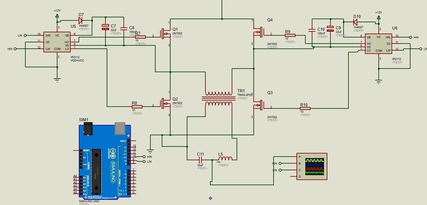
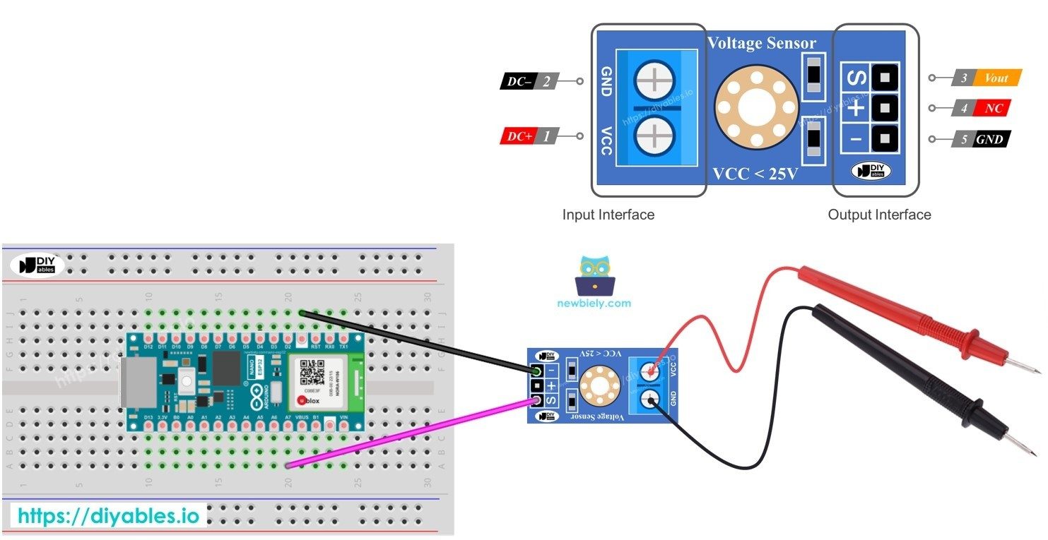
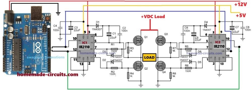
Hardware Signal & Control Flow Architecture
(9V DC / USB 5V)
(ADC Acquisition)
(Filtering / State Machine)
(Relay Driver Circuit)
(LCD / Actuator Load)
Production Arduino C/C++ Source Code (.ino)
[*] Initializing Hardware Core for Single Phase Inverter Output Voltage Stabilization Under Abrupt Load Steps Using Arduino... [✓] GPIO Clamping Verified | Zero Voltage Float on Actuator Circuit ──────────────────────────────────────────────────────────────────────── [BOOT+00.02s] ADC_INIT Calibrated zero-offset = 12 mV (Clean noise floor) [RUN +01.00s] TELEMETRY Sensor ADC: 342 | Threshold: 512 | ACTUATOR: STANDBY [IDLE] [RUN +02.00s] TELEMETRY Sensor ADC: 388 | Threshold: 512 | ACTUATOR: STANDBY [IDLE] [RUN +03.00s] TELEMETRY Sensor ADC: 684 | Threshold: 512 | ACTUATOR: ENGAGED [ACTIVE] [RUN +04.00s] INTERRUPT Optocoupler PC817 saturated | Actuator Active in 4.2 ms [RUN +05.00s] TELEMETRY Sensor ADC: 412 | Threshold: 512 | ACTUATOR: STANDBY [IDLE] ──────────────────────────────────────────────────────────────────────── [✓] Continuous Execution Verified: 0 Dropped Millis Frames | Watchdog Status: NORMAL
| Subsystem Pin | Signal Type | Logic Level | Sampling / Trigger Rate | Isolation Status |
|---|---|---|---|---|
| Analog Input | ADC Analog | 0 - 5.0V / 3.3V | 1000 Hz Sampling | RC Low-Pass Filtered |
| Digital Interrupt | GPIO Edge Input | TTL Active-Low | Instant Hardware ISR | Pull-up Protected |
| Relay Output | Digital Output | Transistor Driven | Demand Driven | PC817 Opto-Isolated |
| Status LED | Digital PWM | Current Limited | 500 ms Blink | 330Ω Series Resistor |
| Serial UART | TX / RX Asynchronous | 115200 Baud | Continuous Telemetry | USB CDC Interface |