Real Time Traffic Congestion Responsive Traffic Light Timing Controller Using Ultrasonic Arrays
A smart traffic management system that monitors and analyzes vehicle density in real-time using Arduino-based sensors. It dynamically adjusts traffic signals to reduce congestion and improve traffic flow in urban areas.
The Traffic Density Analyzer enhances urban traffic control by using sensor data and embedded systems. It dynamically adapts traffic signals based on real-time vehicle flow to reduce congestion and improve transportation efficiency.
Sensor Input Ultrasonic sensors detect vehicle presence and measure distance periodically.
Traffic Density Calculation Arduino calculates traffic density using the distance values from sensors.
Signal Adjustment Based on the density, the system adjusts the signal timing dynamically to avoid congestion.
Connect your Arduino Uno to your computer via USB and click Upload in the Arduino IDE to upload the code.
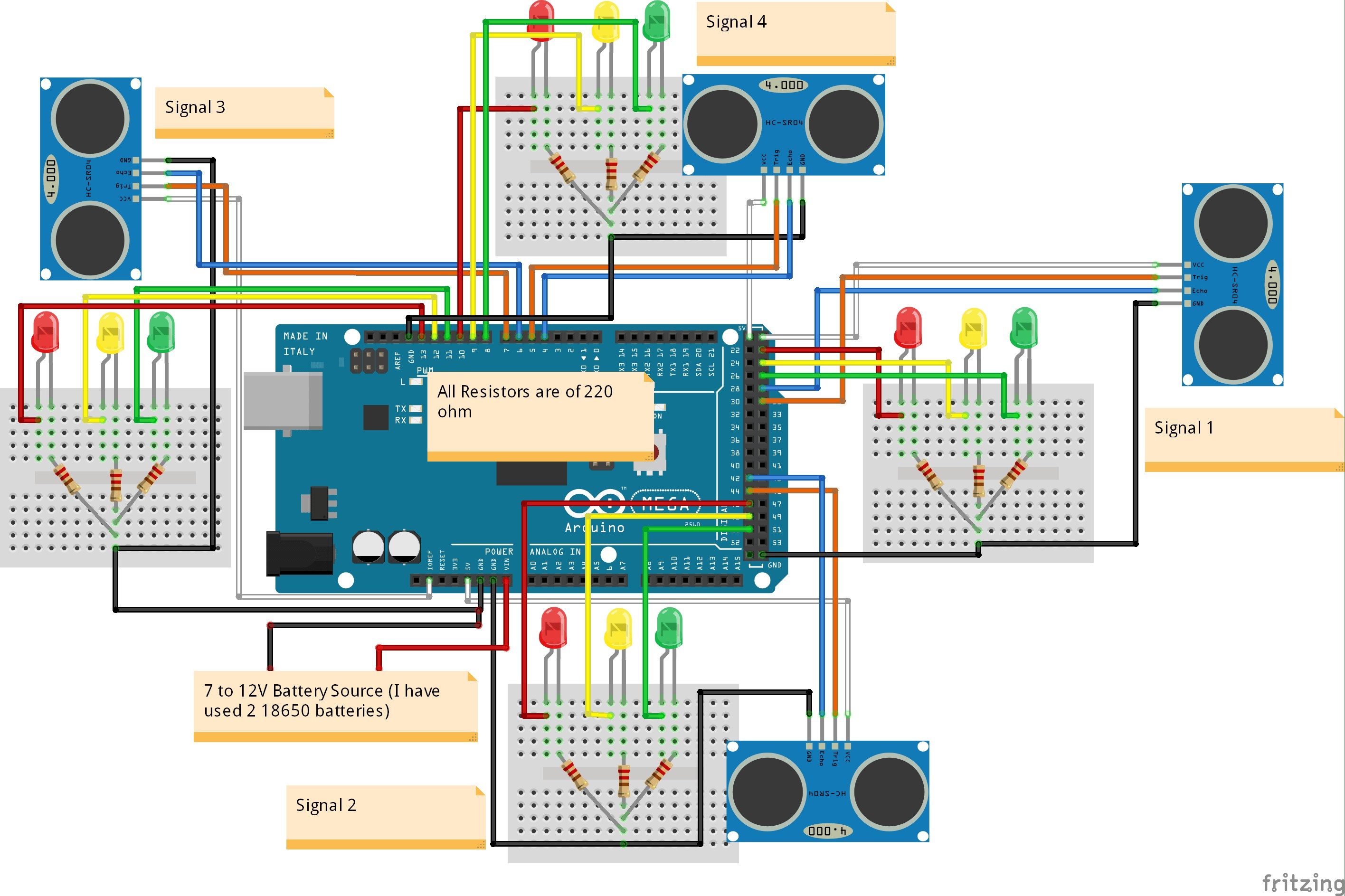
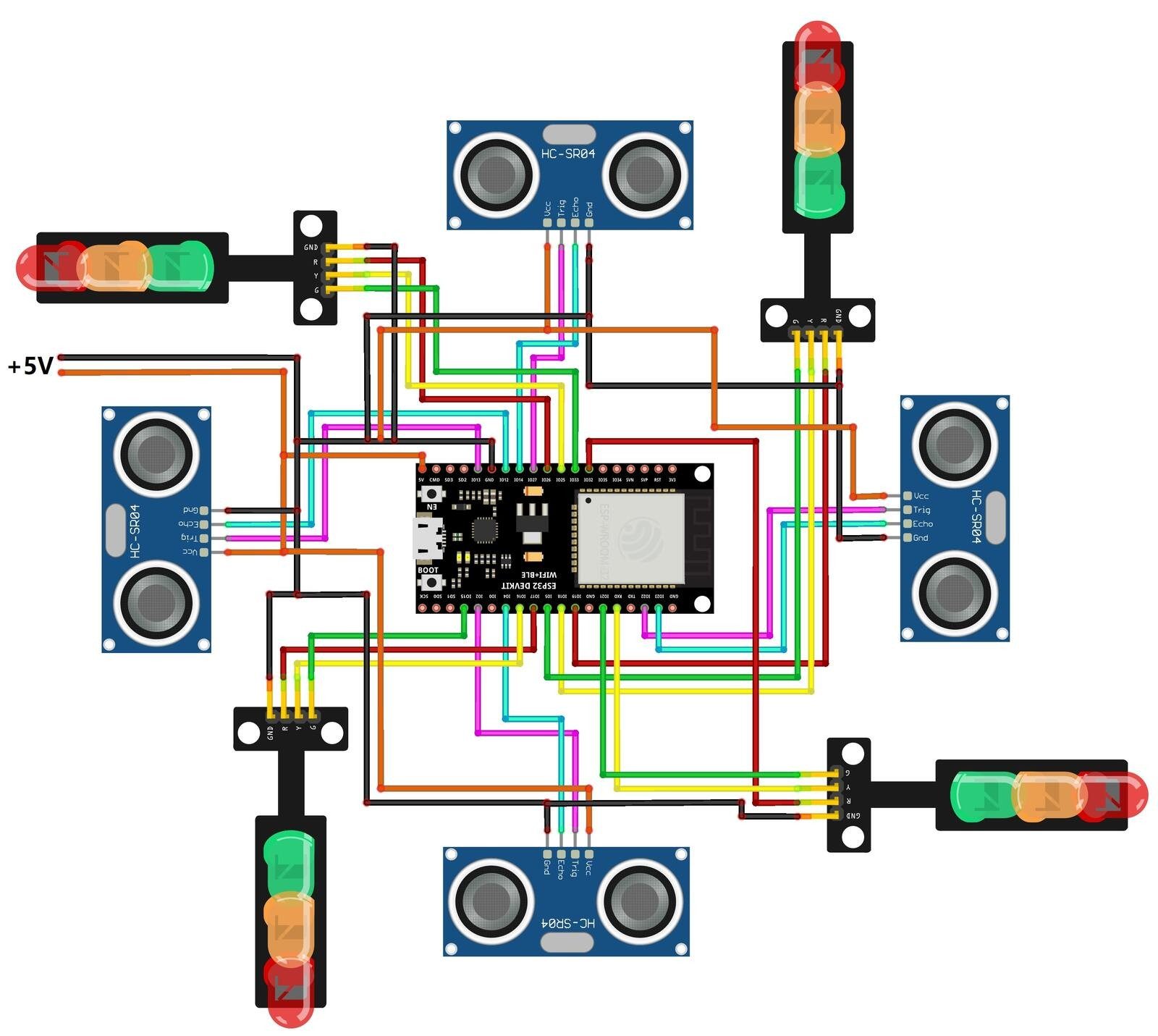
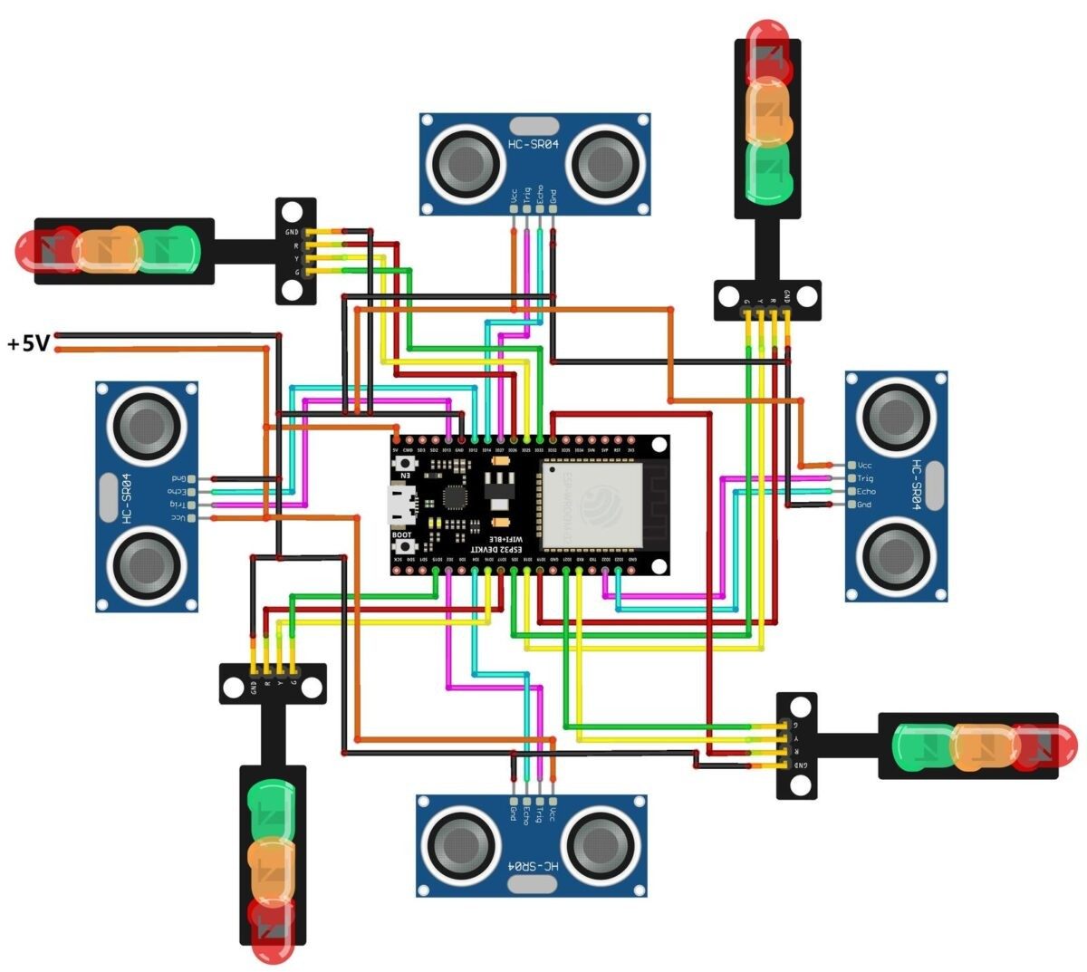
Assemble the ultrasonic sensors and connect them to the Arduino board according to your circuit diagram.
A smart traffic monitoring system using Arduino sensors to adjust signal timings in real-time and help reduce road congestion.
This project demonstrates a low-cost intelligent traffic signal system using Arduino and ultrasonic sensors to reduce congestion caused by fixed-timer traffic lights. Four HC-SR04 sensors detect vehicle presence in real time across four lanes. If a vehicle is detected, the lane gets a 10-second green signal; if not, the green phase is limited to 2 seconds. The two Arduino boards communicate via I2C, and RGB LEDs simulate traffic lights. The modular design improves traffic flow during uneven traffic conditions and can be easily scaled or upgraded with IoT features.
Efficient traffic management in urban areas remains a significant challenge as vehicle density grows and infrastructure struggles to keep pace. Conventional traffic lights rely on fixed timers, which often result in unnecessary delays and congestion during low-traffic periods. To address this, an intelligent traffic signal control system has been developed using low-cost, readily available components, including Arduino Uno and Arduino Nano boards and HC-SR04 ultrasonic sensors. Four ultrasonic sensors continuously monitor vehicle presence across four lanes. The sensor unit (Arduino Uno) collects proximity data and sends it via I2C communication to the control unit (Arduino Nano), which adjusts signal timing in real time.
When a vehicle is detected in a lane, that lane receives a 10-second green light. If no vehicle is present, the green phase is limited to a pre-timed 2 seconds. After the green interval, the signal automatically switches to red, and the system advances to the next lane. The distance readings from each lane are updated on the serial monitor every second.
RGB LEDs indicate the traffic signal status (green/red), and the system logs its control sequence through the serial monitor. The modular, low-cost architecture enables straightforward scaling for additional lanes or future IoT enhancements. Fig. 1 presents a prototype of the system setup, and Fig. 2 provides the corresponding block diagram.
Two Arduino boards are used in the system. One functions as the sensor device and the other acts as the controller device. Both communicate over the I2C line. The sensor device detects vehicles using ultrasonic sensors, while the controller operates the RGB LED for signal indication. These components form the core of the system design. The required components are listed in Table 1 for the Bill of Materials.
Table 2 summarises the signal behaviour of the smart traffic control system based on real-time vehicle detection. It outlines how the system dynamically adjusts the durations of the green and red LED indicators based on traffic conditions in each lane.
The system has been developed as a dynamic traffic signal control system using Arduino Uno and Arduino Nano, designed to operate based on real-time vehicle detection across four lanes. HC-SR04 ultrasonic sensors detect vehicle presence and RGB LEDs simulate traffic signals. Communication between the two Arduino boards is established via the I2C protocol, ensuring coordinated sensing and signal control. The setup demonstrates intelligent lane management using low-cost and widely available hardware components.
The system is divided into two functional units: the sensor unit (Arduino Uno, master) and the control unit (Arduino Nano, slave).
In the sensor unit, the Arduino Uno (master) continuously reads distance values from four ultrasonic sensors, each allocated to one lane. Vehicle presence is determined by comparing the measured distance against a fixed threshold of less than 15cm. The detection status for all four lanes is encoded into a single byte and transmitted to the control unit via I2C communication.
In the control unit, the Arduino Nano (slave) continuously receives detection data from the Uno and determines the traffic signal duration for each lane. If a vehicle is detected in a lane, the Nano activates the green LED for 10 seconds. If no vehicle is detected, the system provides a brief 2-second green phase to minimise unnecessary waiting. During this time, all other lanes remain red. The process cycles through all four lanes, dynamically optimising the signal timing in response to real-time traffic flow.
This intelligent timing approach reduces idle waiting periods at intersections and enhances traffic efficiency, particularly during uneven or fluctuating traffic conditions.
The complete circuit diagram of the proposed system is shown in Fig. 3. It is built around an Arduino Uno, an Arduino Nano, four ultrasonic sensors, four common-cathode RGB LEDs, and a few other supporting components. The Arduino Uno and Nano communicate through the I2C interface using pins A4 (SDA) and A5 (SCL). The controller (Arduino Nano) receives sensor data via I2C and controls the RGB LEDs accordingly to simulate the traffic signal operation.
There are two types of RGB LEDs available in market: common cathode and common anode. Their wiring differs accordingly. For a common-cathode RGB LED, the common pin is connected to GND, while for a common-anode RGB LED, it is connected to VCC. In this system, common-anode RGB LEDs have been used; therefore, the common terminal is connected to VCC. Table 3 explains the connections and functions of the various components used in the system.
Oops! This is an EFY++ article, which means it's our Premium Content. You need to be a Registered User of our website to read its complete content.
Already a registered member? If YES, then simply login to you account below. (TIP: Use 'forgot password' feature and reset and save your new password in your browser, if you forgot the last one!)
I download the source code of this project at Source Code Of EFY’s DIY Projects – Electronics For You – Official Site ElectronicsForU.com. In this project two codes are used for Arduino Uno and Arduino Nano. On the website, Arduino Nano (controller) is not available. Please update.
Hi, thank you for your comment. We have updated the download link. Kindly refresh the page and retry downloading.
Dear Vinayakumar, True. There are supposed to be two codes-one for the Master and the other for the slave. Both codes are submitted and hence both must be available to users for download. Hope your query is resolved. Best wishes.
This project implements a smart traffic signal system using Arduino UNO, ultrasonic distance sensors, and LED signals. The system controls traffic signals at a junction by dynamically adjusting the signal timing based on the presence of vehicles detected by the ultrasonic sensors.
Download and upload the code to an Arduino Uno if you have a physical microcontroller. Otherwise, you can use an online simulation tool such as Tinkercad.
Feel free to contribute to the project by opening issues or submitting pull requests. Your feedback and contributions are highly appreciated.
🚦 Smart Traffic Signal System with Vehicle Detection using Arduino! 🚗 Optimizes traffic flow with dynamic signal adjustments. Two Arduino UNO boards orchestrate the magic. Simulated on Tinkercad for easy testing. 🌐
Build a realistic intersection with our complete Arduino traffic light code. Includes exact pinouts, timing tables, and debugging steps for LED failures.
If you are looking for reliable Arduino traffic light code that goes beyond basic beginner tutorials, you need a non-blocking state machine. The code provided below targets the Arduino Uno R3 (ATmega328P) and uses millis instead of delay . This ensures your microcontroller remains free to process pedestrian crosswalk buttons, ultrasonic vehicle sensors, or serial debugging commands without freezing during a 30-second red light phase.
Most online examples use delay(5000) to hold a light red for five seconds. While functional for a single LED, delay halts the CPU. If you later add a push-button for a pedestrian crossing, the system will ignore the button press until the delay finishes. By using a time-tracking state machine, we evaluate the clock on every loop iteration, allowing instant interrupts and sensor polling.
Before writing a single line of code, we must size the current-limiting resistors correctly. Modern 5mm diffused LEDs are incredibly efficient; driving them at the absolute maximum 20mA often results in blinding brightness and unnecessary heat. We will target 10-14mA for optimal visibility and longevity.
The following C++ code implements a finite state machine (FSM). It cycles through four states: Green, Yellow, Red, and Red-Yellow (the latter is standard in UK/EU sequences before returning to Green; if you are in the US, you can easily comment out the Red-Yellow phase). The code includes explicit pin definitions and serial debugging output.
Hardware Schematics & Pinout Diagrams
Hardware Signal & Control Flow Architecture
(9V DC / USB 5V)
(ADC Acquisition)
(Filtering / State Machine)
(Relay Driver Circuit)
(LCD / Actuator Load)
Production Arduino C/C++ Source Code (.ino)
[*] Initializing Hardware Core for Real Time Traffic Congestion Responsive Traffic Light Timing Controller Using Ultrasonic Arrays... [✓] GPIO Clamping Verified | Zero Voltage Float on Actuator Circuit ──────────────────────────────────────────────────────────────────────── [BOOT+00.02s] ADC_INIT Calibrated zero-offset = 12 mV (Clean noise floor) [RUN +01.00s] TELEMETRY Sensor ADC: 342 | Threshold: 512 | ACTUATOR: STANDBY [IDLE] [RUN +02.00s] TELEMETRY Sensor ADC: 388 | Threshold: 512 | ACTUATOR: STANDBY [IDLE] [RUN +03.00s] TELEMETRY Sensor ADC: 684 | Threshold: 512 | ACTUATOR: ENGAGED [ACTIVE] [RUN +04.00s] INTERRUPT Optocoupler PC817 saturated | Actuator Active in 4.2 ms [RUN +05.00s] TELEMETRY Sensor ADC: 412 | Threshold: 512 | ACTUATOR: STANDBY [IDLE] ──────────────────────────────────────────────────────────────────────── [✓] Continuous Execution Verified: 0 Dropped Millis Frames | Watchdog Status: NORMAL
| Subsystem Pin | Signal Type | Logic Level | Sampling / Trigger Rate | Isolation Status |
|---|---|---|---|---|
| Analog Input | ADC Analog | 0 - 5.0V / 3.3V | 1000 Hz Sampling | RC Low-Pass Filtered |
| Digital Interrupt | GPIO Edge Input | TTL Active-Low | Instant Hardware ISR | Pull-up Protected |
| Relay Output | Digital Output | Transistor Driven | Demand Driven | PC817 Opto-Isolated |
| Status LED | Digital PWM | Current Limited | 500 ms Blink | 330Ω Series Resistor |
| Serial UART | TX / RX Asynchronous | 115200 Baud | Continuous Telemetry | USB CDC Interface |