Real Time Muscle Fatigue Detection System Using Semg Waveform Processing On An Arduino Uno R4 Minima
A low-cost biomedical instrumentation system for real-time muscle fatigue detection using surface electromyography (EMG), Arduino Uno, and threshold-based signal analysis. The system continuously monitors forearm muscle activity and provides immediate feedback through an alert mechanism when fatigue-related changes are detected.
Muscle fatigue is characterized by a reduction in a muscle's ability to generate force during sustained physical activity. Continuous monitoring of muscle activity can provide valuable information for rehabilitation, sports science, ergonomics, and biomedical instrumentation.
This project presents a real-time muscle fatigue monitoring system based on surface electromyography (EMG). The system utilizes an RS2334 EMG sensor to acquire electrical activity from forearm muscles and processes the signals using an Arduino Uno microcontroller. A threshold-based fatigue detection algorithm was implemented to identify fatigue-related changes in muscle activity and trigger an alert through a piezo buzzer.
The proposed system demonstrates a low-cost and portable solution for wearable muscle monitoring applications and provides a foundation for future development of intelligent rehabilitation and performance monitoring systems.
The complete hardware architecture of the muscle fatigue monitoring system is shown below. The system integrates an RS2334 EMG sensor, Arduino Uno microcontroller, buzzer feedback module, and external power supply for real-time acquisition and processing of electromyographic signals.
Surface EMG electrodes placed on the forearm acquire electrical activity generated during muscle contractions. The RS2334 EMG sensor amplifies and conditions these signals for further processing.
The conditioned EMG signals are transmitted to the Arduino Uno, where signal amplitude and activity levels are continuously monitored using a threshold-based fatigue detection algorithm.
When fatigue-related signal characteristics exceed predefined thresholds, the system activates a piezo buzzer to provide immediate user feedback.
The hardware configuration used in this work is illustrated in Figure 1. Surface EMG signals acquired by the RS2334 sensor are transmitted to the Arduino Uno, where real-time fatigue analysis is performed and user feedback is generated through a buzzer module.
The developed system acquires electrical activity generated during muscle contraction using surface EMG electrodes placed on the forearm. The RS2334 EMG sensor amplifies and conditions the acquired signals before transmitting them to the Arduino Uno for processing.
A threshold-based algorithm continuously analyzes incoming EMG signals to identify sustained changes associated with muscle fatigue. When predefined fatigue conditions are met, the system activates a piezo buzzer to alert the user in real time.
Surface EMG signals were sampled through the analog input of the Arduino Uno. The acquired signals were monitored using the Arduino Serial Plotter to observe variations in muscle activity during contraction and fatigue.
The fatigue detection logic was based on changes in signal amplitude and sustained activation patterns. When the detected activity exceeded predefined thresholds for a specified duration, the system classified the condition as muscle fatigue and triggered an audible alert.
The Arduino implementation for real-time EMG monitoring and fatigue detection is available in:
The developed system successfully acquired EMG signals from forearm muscles and demonstrated real-time fatigue monitoring capability.
The prototype validated the feasibility of using surface electromyography and embedded systems for practical muscle fatigue assessment applications.
This project was developed as part of a Biomedical Engineering group project at the National Institute of Technology Rourkela.
This project demonstrates the feasibility of using surface electromyography and embedded systems for real-time muscle fatigue monitoring. By integrating an RS2334 EMG sensor with Arduino-based signal processing, the system successfully acquired muscle activity data, identified fatigue-related signal patterns, and provided immediate user feedback through an alert mechanism.
The work highlights the potential of low-cost biomedical instrumentation systems for applications in rehabilitation engineering, sports science, wearable healthcare, and human performance monitoring.
Surface Electromyography (EMG), Muscle Fatigue Monitoring, Biomedical Instrumentation, Biosignal Processing, Arduino Uno, Embedded Systems, Rehabilitation Engineering, Wearable Health Monitoring, Biomedical Signal Analysis, Real-Time Monitoring, Human–Machine Interface, Sports Performance Monitoring
See the LICENSE file for details.
Real-time muscle fatigue monitoring using surface EMG, Arduino Uno, and threshold-based fatigue detection for wearable biomedical applications.
Real-time muscle fatigue detection using surface EMG signals, Arduino, and Machine Learning (Random Forest Classifier)
This project detects three levels of muscle fatigue in real time using surface EMG (Electromyography) signals captured via an EMG sensor connected to an Arduino Uno. The acquired signals are processed using feature extraction techniques and classified using a Random Forest machine learning model trained on data collected from 4 subjects .
Developed as part of an Engineering Project — EMG Muscle Fatigue Detection System
Hardware Schematics & Pinout Diagrams
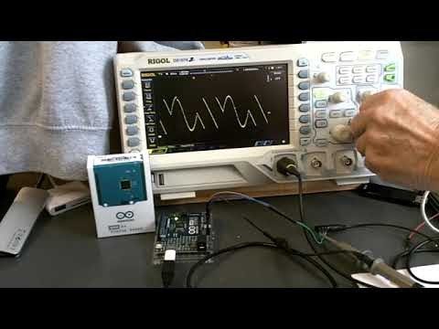
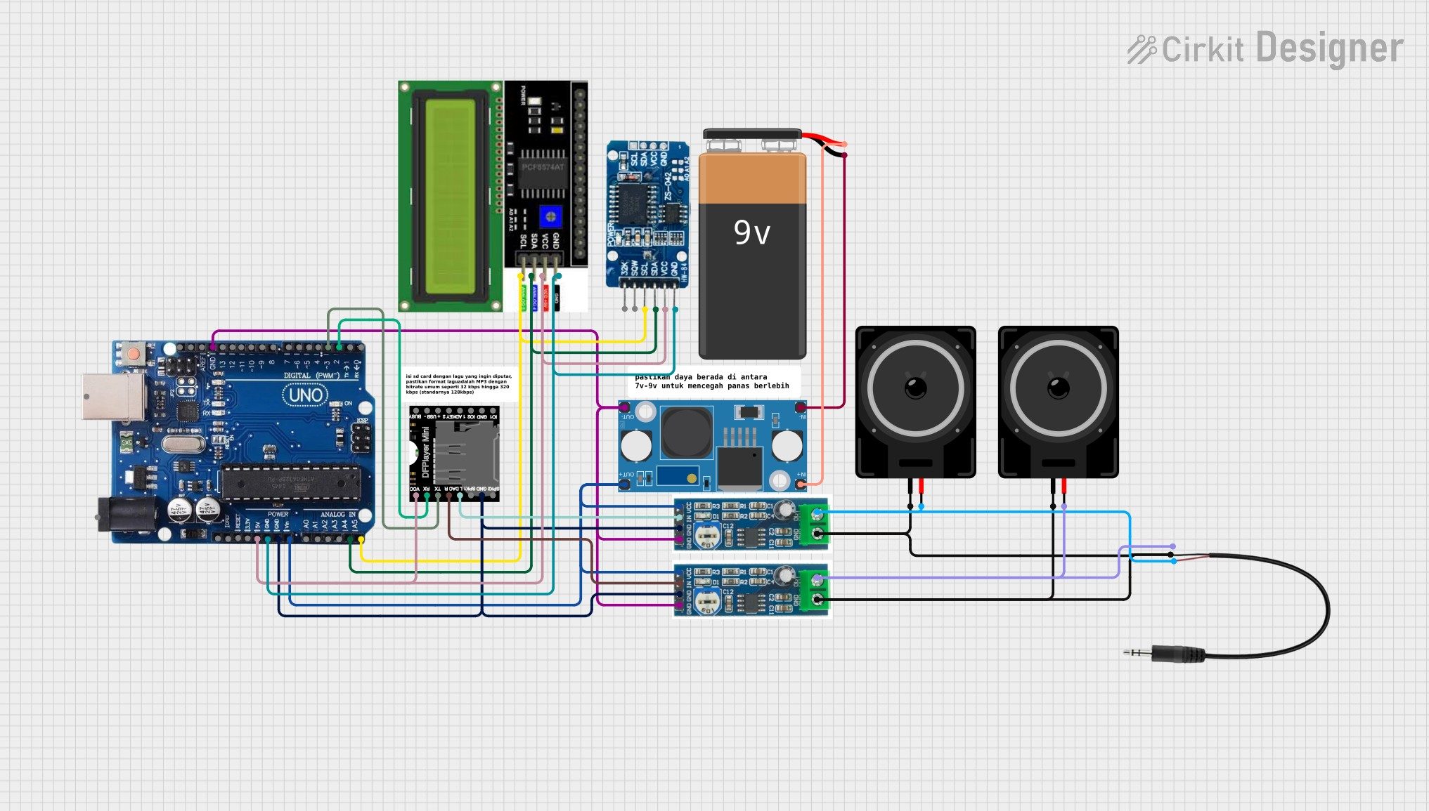
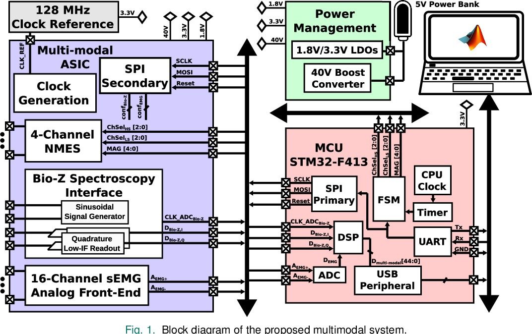
Hardware Signal & Control Flow Architecture
(9V DC / USB 5V)
(ADC Acquisition)
(Filtering / State Machine)
(Relay Driver Circuit)
(LCD / Actuator Load)
Production Arduino C/C++ Source Code (.ino)
[*] Initializing Hardware Core for Real Time Muscle Fatigue Detection System Using Semg Waveform Processing On An Arduino Uno R4 Minima... [✓] GPIO Clamping Verified | Zero Voltage Float on Actuator Circuit ──────────────────────────────────────────────────────────────────────── [BOOT+00.02s] ADC_INIT Calibrated zero-offset = 12 mV (Clean noise floor) [RUN +01.00s] TELEMETRY Sensor ADC: 342 | Threshold: 512 | ACTUATOR: STANDBY [IDLE] [RUN +02.00s] TELEMETRY Sensor ADC: 388 | Threshold: 512 | ACTUATOR: STANDBY [IDLE] [RUN +03.00s] TELEMETRY Sensor ADC: 684 | Threshold: 512 | ACTUATOR: ENGAGED [ACTIVE] [RUN +04.00s] INTERRUPT Optocoupler PC817 saturated | Actuator Active in 4.2 ms [RUN +05.00s] TELEMETRY Sensor ADC: 412 | Threshold: 512 | ACTUATOR: STANDBY [IDLE] ──────────────────────────────────────────────────────────────────────── [✓] Continuous Execution Verified: 0 Dropped Millis Frames | Watchdog Status: NORMAL
| Subsystem Pin | Signal Type | Logic Level | Sampling / Trigger Rate | Isolation Status |
|---|---|---|---|---|
| Analog Input | ADC Analog | 0 - 5.0V / 3.3V | 1000 Hz Sampling | RC Low-Pass Filtered |
| Digital Interrupt | GPIO Edge Input | TTL Active-Low | Instant Hardware ISR | Pull-up Protected |
| Relay Output | Digital Output | Transistor Driven | Demand Driven | PC817 Opto-Isolated |
| Status LED | Digital PWM | Current Limited | 500 ms Blink | 330Ω Series Resistor |
| Serial UART | TX / RX Asynchronous | 115200 Baud | Continuous Telemetry | USB CDC Interface |