Real Time Emergency Impact And Rollover Fuelbattery Cut Off Switch For Electric Two Wheelers
In this post I will show how to construct a battery eliminator / DC variable power supply which will automatically cut-off the supply, if the current flow through the load exceeds the preset threshold level.
The proposed over current cut-off power supply circuit using Arduino has 16 X 2 LCD display, which is used to show case the voltage, current, power consumption and preset threshold current limit in real time.
Being an electronics enthusiast, we test our prototypes on a variable voltage power supply . Most of us own a cheap variable power supply which might don’t sport neither voltage measuring / current measuring feature nor short circuit or over current protection built in.
That’s because power supply with these mentioned features can bomb on your wallet and will be overkilled for hobby usage.
Short circuit and over current flow is a problem for beginners to professionals and beginners are prone to this more often because of their inexperience, they might reverse the power supply’s polarity or connect the components in wrong way, etc.
These things can cause the current flow through the circuit unusually high , resulting in thermal runaway in semiconductor and passive components which results in destruction of valuable electronic components. In these cases ohm’s law turns into an enemy.
If you never made a short circuit or fried circuit, then congrats! You are one of few people who are perfect in electronics or you never try something new in electronics.
The proposed power supply project can protect the electronic components from such frying destruction, which will be cheap enough for an average electronics hobbyist and easy enough to construct one for who is slightly above beginner level.
The power supply has 3 potentiometers: one for adjusting the LCD display contrast, one for adjusting the output voltage ranging from 1.2 V to 15V and the last potentiometer is used for setting the current limit ranging from 0 to 2000 mA or 2 Ampere.
The LCD display will update you with four parameters every second: the voltage, current consumption, pre-set current limit and power consuming by the load.
The current consumption via load will be displayed in milliamps; the pre-set current limit will be displayed in milliamps and the power consumption will be displayed in milli-watts.
The circuit is divided into 3 parts: the power electronics, the LCD display connection and power measuring circuit.
These 3 stage may help the readers to understand the circuit better. Now let’s see the power electronics section which controls the output voltage.
The 12v -0-12v / 3A transformer will be utilized for stepping down the voltage, the 6A4 diodes will convert the AC into DC voltage and the 2000uF capacitor will smooth out the choppy DC supply from diodes.
The LM 7809 fixed 9V regulator will convert the unregulated DC to regulated 9V DC supply.
The 9V supply will power the Arduino and relay . Try to use a DC jack for arduino’s input supply.
Don’t skip those 0.1uF ceramic capacitors which provide good stability for output voltage.
The LM 317 provides variable output voltage for the load which is to be connected.
There is nothing to explain here much, just wire up the Arduino and LCD display as per the circuit diagram. Adjust the 10K potentiometer for better viewing contrast.
The Arduino can measure voltage and current simultaneously by connecting the network of resistors as per the circuit diagram.
The four 10 ohm resistors in parallel which forms 2.5 ohm shunt resistor which will be utilized for measuring the current flow through the load.
The 10k ohm and 100k ohm resistors helps the Arduino to measure voltage at the load. These resistor can be one with normal wattage rating.
If you want to know more about the working of Arduino based ammeter and voltmeter check out these two links:
Voltmeter: https://www.homemade-circuits.com/2016/09/how-to-make-dc-voltmeter-using-arduino.html
Ammeter: https://www.homemade-circuits.com/2017/08/arduino-dc-digital-ammeter.html
The 10K ohm potentiometer is provided for adjusting the maximum current level at the output.
If the current flow through the load exceeds the pre-set current the output supply will be disconnected.
You can see the preset level in the display it will be mentioned as “LT” (Limit).
Say for example: if you set the limit as 200, it will gives out current till 199mA. If the current consumption gets equal to 200 mA or above the output will be immediately cut-off.
When this pin is high the transistor energizes the relay which connects the common and normally open pins, which conducts the positive supply for the load.
The diode IN4007 absorbs the high voltage back EMF from the relay coil while switching the relay ON and OFF.
By now, you would have gained enough knowledge to construct a power supply which protect you valuable electronic components and modules.
If you have any specific question regarding this over current cut-off power supply circuit using Arduino feel free to ask in comment section, you may receive a quick reply.
I have a few problems and would like to share with you. Can you help me understand the connection of 4.7k Potentiometer and LM317? Can I use 12V relay instead of 9V relay and do I need to change LM7809 to get 12V? Will there be any problem if I use 0.1uF normal capacitor instead of ceramic capacitor? How do I set the value of LT?
I will be grateful if you help me understand the confusions. Thanks for this amazing platform.
Hi Jahir, Please see the following enlarged diagram and I hope you will be able to see the connections correctly here: Yes you can use 12V relay, and for that you will have to replace the 7809 with 7812. You can use any 0.1uF capacitor, just make sure it is non-polar… Where is LT? I can’t seem to find it…
GOOD DAY SIR! PLEASE I WOULD LIKE YOU WRITE A CODE FOR AC LOAD MONITORING USING ARDUINO UNO. THE POWER LIMIT OF THE LOAD WILL BE SET USING PUSH BUTTONS. THERE WILL BE WARNING ALARM AS SOON AS THE LIMIT IS REACHED FOR 3 TIMES AFTER WHICH THE LOAD WILL BE SHUTDOWN. THE PROCESSES WILL BE SHUN ON THE LCD THROUGH I2C.
HELLO SIR! THANK YOU SO MUCH FOR THE CODE AND INSTRUCTIONS YOU SENT TO ME.I APPRECIATE. SIR WHAT I ACTUALLY WANTED IS THE LOAD MONITORING IN WATTAGE. THAT IS WHERE A PARTICULAR LOAD LIMIT WILL BE SET IN WATTAGE. THAT WILL ENABLE ME TO SET A PARTICULAR POWER LIMIT A GIVEN APARTMENT WILL CARRY. SO WHAT MODIFICATIONS CAN BE MADE TO ACHIEVE THAT BASED ON THE CODE YOU SENT TO ME BECAUSE POWER = CURRENTX VOLTAGE. LETS SAY I WANT TO LIMIT THE LOAD AT 500W OR ANYTHING ELSE . AGAIN I INTEND TO THE TYPE OF CURRENT SENSOR TYPICAL OC COMMERCIAL INVERTERS THAT CAN HANDLE UP TO 100A.
Moses! I have requested my friend to design it, let’s see if he is able to create the necessary code for this function or not…once done I will let you know…
Moses, I have posted the full article in the following link, hope it is as per your requirement. If you have any further questions, please post it under the below article: https://www.homemade-circuits.com/100a-ac-load-monitoring-circuit-using-arduino-watt-limit-lcd-alarm-auto-shutdown/
THANK YOU SO MUCH SIR. YOU HAVE BEEN HELPFUL TO ME . I AM EAGERLY WAITING FOR IT SIR.
Here’s the complete code. ACS712 OUT = connect to A0 Button1 (Increase) = connect to D2 (Pull-down 10k to GND) Button2 (Decrease) = connect to D3 (Pull-down 10k to GND) Buzzer = connect to D4 Relay module IN = connect to D5 LCD SDA = connect to A4 LCD SCL = connect to A5 ACS712 VCC/GND, Relay VCC/GND, Buzzer = Connect to Arduino 5V/GND
#include #include #define CURRENT_SENSOR A0 #define BUTTON_UP 2 #define BUTTON_DOWN 3 #define BUZZER 4 #define RELAY 5 LiquidCrystal_I2C lcd(0x27, 16, 2); float current = 0; int limit = 2; // Default current limit in Amps int overCount = 0; bool loadOn = true; unsigned long lastRead = 0; void setup { pinMode(BUTTON_UP, INPUT); pinMode(BUTTON_DOWN, INPUT); pinMode(BUZZER, OUTPUT); pinMode(RELAY, OUTPUT); digitalWrite(RELAY, HIGH); // Relay ON lcd.begin; lcd.backlight; lcd.setCursor(0,0); lcd.print("AC Load Monitor"); delay(2000); lcd.clear; } void loop { // Button press handling if (digitalRead(BUTTON_UP) == HIGH) { limit++; delay(300); } if (digitalRead(BUTTON_DOWN) == HIGH) { if (limit > 1) limit--; delay(300); } // Read current every 1 second if (millis - lastRead > 1000) { lastRead = millis; current = readCurrent; // Measure current lcd.clear; lcd.setCursor(0, 0); lcd.print("I:"); lcd.print(current, 1); lcd.print("A Lim:"); lcd.print(limit); lcd.setCursor(0, 1); if (loadOn) { lcd.print("Load ON "); } else { lcd.print("Load OFF"); } // Check overload if (current > limit && loadOn) { beep; overCount++; lcd.setCursor(10,1); lcd.print("Warn:"); lcd.print(overCount); if (overCount >= 3) { loadOn = false; digitalWrite(RELAY, LOW); // Turn off load lcd.setCursor(0,1); lcd.print("Overload Shutdown "); } } } } // Simulated average current read from ACS712 float readCurrent { long sum = 0; for (int i = 0; i < 150; i++) { sum += analogRead(CURRENT_SENSOR); delay(2); } float voltage = (sum / 150.0) * (5.0 / 1023.0); float current = (voltage - 2.5) / 0.1; // For ACS712-20A (100mV/A) if (current < 0) current = 0; return current; } void beep { digitalWrite(BUZZER, HIGH); delay(200); digitalWrite(BUZZER, LOW); }
Hardware Schematics & Pinout Diagrams
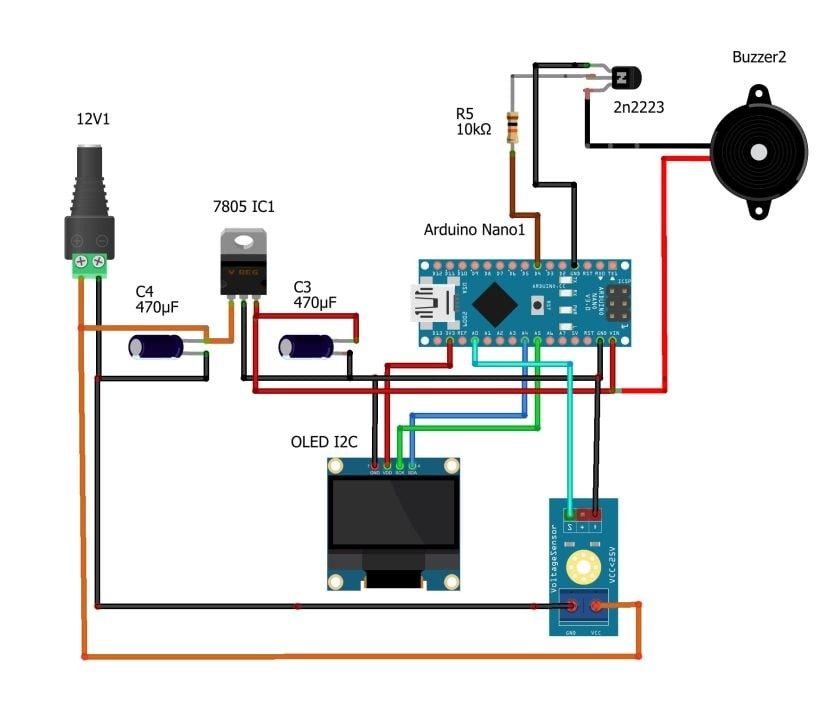

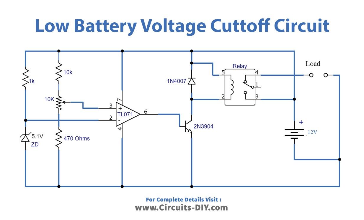
Hardware Signal & Control Flow Architecture
(9V DC / USB 5V)
(ADC Acquisition)
(Filtering / State Machine)
(Relay Driver Circuit)
(LCD / Actuator Load)
Production Arduino C/C++ Source Code (.ino)
[*] Initializing Hardware Core for Real Time Emergency Impact And Rollover Fuelbattery Cut Off Switch For Electric Two Wheelers... [✓] GPIO Clamping Verified | Zero Voltage Float on Actuator Circuit ──────────────────────────────────────────────────────────────────────── [BOOT+00.02s] ADC_INIT Calibrated zero-offset = 12 mV (Clean noise floor) [RUN +01.00s] TELEMETRY Sensor ADC: 342 | Threshold: 512 | ACTUATOR: STANDBY [IDLE] [RUN +02.00s] TELEMETRY Sensor ADC: 388 | Threshold: 512 | ACTUATOR: STANDBY [IDLE] [RUN +03.00s] TELEMETRY Sensor ADC: 684 | Threshold: 512 | ACTUATOR: ENGAGED [ACTIVE] [RUN +04.00s] INTERRUPT Optocoupler PC817 saturated | Actuator Active in 4.2 ms [RUN +05.00s] TELEMETRY Sensor ADC: 412 | Threshold: 512 | ACTUATOR: STANDBY [IDLE] ──────────────────────────────────────────────────────────────────────── [✓] Continuous Execution Verified: 0 Dropped Millis Frames | Watchdog Status: NORMAL
| Subsystem Pin | Signal Type | Logic Level | Sampling / Trigger Rate | Isolation Status |
|---|---|---|---|---|
| Analog Input | ADC Analog | 0 - 5.0V / 3.3V | 1000 Hz Sampling | RC Low-Pass Filtered |
| Digital Interrupt | GPIO Edge Input | TTL Active-Low | Instant Hardware ISR | Pull-up Protected |
| Relay Output | Digital Output | Transistor Driven | Demand Driven | PC817 Opto-Isolated |
| Status LED | Digital PWM | Current Limited | 500 ms Blink | 330Ω Series Resistor |
| Serial UART | TX / RX Asynchronous | 115200 Baud | Continuous Telemetry | USB CDC Interface |