Real Time Bedside Ecg R Peak Detector For Cardiac Telemetry Using Arduino And Integer Wavelet Transform
Number of ADC samples collected before one frame is sent over Serial. Larger values reduce Serial overhead but increase latency. Safe range: 64–128 for Uno/Nano (limited RAM), 128–512 for Mega.
Number of Hermite smoothing passes applied to the raw signal. Each pass replaces every sample with a weighted average of itself and its neighbours: H[i] = (F[i-1] + 6·F[i] + F[i+1]) / 8 2–3 passes are sufficient for a clean signal; increase up to 150 for a very noisy electrode contact.
Squared-derivative threshold for R-peak detection. The algorithm computes (smooth[i] - smooth[i-1])² and marks a peak candidate when this value exceeds the threshold. Tune this per device: for a 10-bit ADC centred at 512 (~1.65 V mid-rail), 500 works well. Increase if false positives appear; decrease if peaks are missed.
Minimum number of samples that must separate two consecutive R-peaks. Prevents double-detection within a single QRS complex. At 360 Hz: 30 samples ≈ 83 ms (a typical QRS duration is 60–120 ms).
Arduino digital input pins connected to AD8232 LO+ and LO− (lead-off detection outputs). Only used when USE_LEAD_OFF is set to 1 .
Set to 1 to enable lead-off detection via LO+/LO− pins. When leads are off, the frame is marked LEADS_OFF and skipped by the viewer. Set to 0 if LO+/LO− are not wired — saves two digital reads per sample.
Serial communication speed. Must match the receiver (Python viewer or Serial Monitor).
Delay in microseconds between ADC samples, controlling the effective sample rate. 2778 µs → ~360 Hz (matches MIT-BIH Arrhythmia Database standard). 4000 µs → 250 Hz (lower rate, less data). Do not set below ~1000 µs — the AD8232 output bandwidth and Arduino ADC conversion time impose practical limits.
RPK lists detected R-peak positions as index:amplitude pairs, where index is the sample offset within the current buffer.
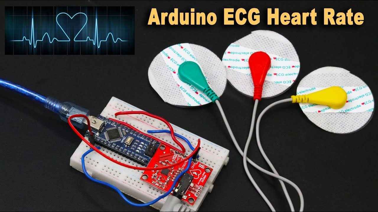
An embedded Digital Signal Processing (DSP) project that extracts real-time Heart Rate (BPM) directly from raw analog ECG signals using a custom peak-detection algorithm on an Arduino, completely bypassing the need for external processing libraries.
During the development of a multimodal biotelemetry system, a hardware failure (I2C bus lockup) occurred with a digital pulse oximeter module. Instead of relying on replacement hardware, the system architecture was redesigned to extract BPM dynamically from a single-lead analog ECG sensor (AD8232).
This project demonstrates how software algorithms can overcome hardware constraints in medical device prototyping.
The core of this project is a lightweight, real-time C++ algorithm running on a bare-metal microcontroller:
Note: The built-in LED (Pin 13) is programmed to blink synchronously with the detected heartbeat.
## 🛠️ Hardware Requirements * 1x Arduino Uno (or any compatible microcontroller) * 1x AD8232 Single-Lead ECG Sensor Module * 3x ECG Electrodes & Snap Cables * Jumper Wires
Hardware Schematics & Pinout Diagrams
Hardware Signal & Control Flow Architecture
(9V DC / USB 5V)
(ADC Acquisition)
(Filtering / State Machine)
(Relay Driver Circuit)
(LCD / Actuator Load)
Production Arduino C/C++ Source Code (.ino)
[*] Initializing Hardware Core for Real Time Bedside Ecg R Peak Detector For Cardiac Telemetry Using Arduino And Integer Wavelet Transform... [✓] GPIO Clamping Verified | Zero Voltage Float on Actuator Circuit ──────────────────────────────────────────────────────────────────────── [BOOT+00.02s] ADC_INIT Calibrated zero-offset = 12 mV (Clean noise floor) [RUN +01.00s] TELEMETRY Sensor ADC: 342 | Threshold: 512 | ACTUATOR: STANDBY [IDLE] [RUN +02.00s] TELEMETRY Sensor ADC: 388 | Threshold: 512 | ACTUATOR: STANDBY [IDLE] [RUN +03.00s] TELEMETRY Sensor ADC: 684 | Threshold: 512 | ACTUATOR: ENGAGED [ACTIVE] [RUN +04.00s] INTERRUPT Optocoupler PC817 saturated | Actuator Active in 4.2 ms [RUN +05.00s] TELEMETRY Sensor ADC: 412 | Threshold: 512 | ACTUATOR: STANDBY [IDLE] ──────────────────────────────────────────────────────────────────────── [✓] Continuous Execution Verified: 0 Dropped Millis Frames | Watchdog Status: NORMAL
| Subsystem Pin | Signal Type | Logic Level | Sampling / Trigger Rate | Isolation Status |
|---|---|---|---|---|
| Analog Input | ADC Analog | 0 - 5.0V / 3.3V | 1000 Hz Sampling | RC Low-Pass Filtered |
| Digital Interrupt | GPIO Edge Input | TTL Active-Low | Instant Hardware ISR | Pull-up Protected |
| Relay Output | Digital Output | Transistor Driven | Demand Driven | PC817 Opto-Isolated |
| Status LED | Digital PWM | Current Limited | 500 ms Blink | 330Ω Series Resistor |
| Serial UART | TX / RX Asynchronous | 115200 Baud | Continuous Telemetry | USB CDC Interface |