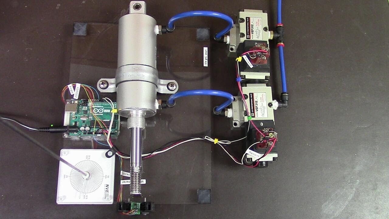
Pneumatic Cylinder Piston Velocity And End Position Sensor Diagnostic Station Via Arduino
Master Arduino piston control with our FAQ and quick reference. Learn wiring, motor drivers, back-EMF protection, and pneumatic setups.
When makers and engineers refer to an Arduino piston setup, they are typically talking about one of two distinct electromechanical systems: DC electric linear actuators (often called electric pistons) or pneumatic air cylinders controlled via solenoid valves. Both require careful power management, inductive load protection, and precise signal switching to operate safely without destroying your microcontroller.
This quick reference guide and FAQ addresses the most common wiring, component selection, and troubleshooting questions for integrating pistons with Arduino boards in 2026.
Selecting the right driver and power supply is critical. Undersizing your components is the leading cause of piston project failure. Below is a quick-selection matrix based on common maker scenarios.
Absolutely not. An Arduino Uno R3 or Nano digital pin can safely source or sink a maximum of 20mA (with an absolute limit of 40mA). A standard 12V electric piston draws anywhere from 3A to 20A under load, and its stall current can briefly exceed 30A. Connecting it directly will instantly vaporize the ATmega328P's internal traces and permanently destroy the board. You must use an intermediary switching device like a high-power motor driver or heavy-duty relays, as detailed in the Arduino Motor and Transistor Guide .
This depends entirely on whether you need positional control (PWM speed/soft stops) or just binary extension/retraction .
When a DC piston stops moving, the collapsing magnetic field in its motor coils generates a massive reverse voltage spike (inductive kickback). This spike travels back through the power rails, causing brownouts that reset your Arduino or frying sensitive logic chips. To prevent this:
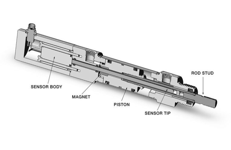
Pneumatic pistons (air cylinders) do not use electricity for motion; they use compressed air (typically 90-120 PSI). The Arduino's job is to control the solenoid valves that route the air. For a standard double-acting pneumatic piston, you need a 5/2-way directional solenoid valve (e.g., the popular 4V210-08 model).
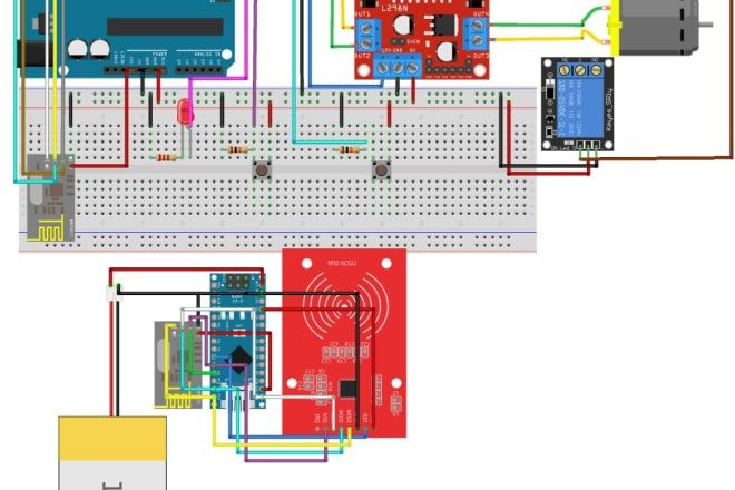
The solenoid coil usually draws 1A to 2A at 12V DC. You can switch this using a logic-level N-channel MOSFET like the IRLZ44N . Wire the Arduino digital pin to the MOSFET gate via a 220Ω resistor, pull the gate to ground with a 10kΩ resistor, and connect the solenoid between the 12V supply and the MOSFET drain. Always place a 1N4007 flyback diode in reverse parallel across the solenoid coil to absorb the inductive spike when the valve closes.
Standard pistons only have limit switches at the end of their stroke. For mid-stroke positioning, you must purchase an actuator with a built-in linear potentiometer (e.g., Progressive Automations PA-14-POT series, which provides excellent wiring diagrams and integration guides ).
This is the classic voltage sag issue. When a piston motor starts, it experiences inrush current (often 3x to 5x its running current). If your power supply cannot deliver this instantaneous current, the voltage drops. If the 12V rail drops below the dropout voltage of the Arduino's onboard regulator (or the external buck converter), the MCU brownout detector triggers a reset.
The Fix: Upgrade your power supply. A standard 12V 5A wall wart will fail. Use an industrial enclosed switching power supply like the Mean Well LRS-350-12 (12V, 29A, ~$45). Additionally, solder a large electrolytic capacitor (e.g., 4700µF 25V) across the main 12V power rails near the motor driver to act as a local energy reservoir during inrush events.
The BTS7960 ICs are often sold on cheap clone boards with inadequate copper pour and undersized heat sinks. While the chip is rated for 43A, those clone boards will thermally throttle or melt at 15A continuous. If your 225lb piston is binding mechanically, it will draw stall current continuously. Ensure your mechanical linkages are aligned, lubricate the actuator's lead screw with white lithium grease, and consider adding a small 40mm cooling fan directly over the BTS7960 heat sink if your application requires high duty cycles.
Before powering up any Arduino piston project for the first time, verify these critical protection measures:
Hardware Schematics & Pinout Diagrams
Hardware Signal & Control Flow Architecture
(9V DC / USB 5V)
(ADC Acquisition)
(Filtering / State Machine)
(Relay Driver Circuit)
(LCD / Actuator Load)
Production Arduino C/C++ Source Code (.ino)
[*] Initializing Hardware Core for Pneumatic Cylinder Piston Velocity And End Position Sensor Diagnostic Station Via Arduino... [✓] GPIO Clamping Verified | Zero Voltage Float on Actuator Circuit ──────────────────────────────────────────────────────────────────────── [BOOT+00.02s] ADC_INIT Calibrated zero-offset = 12 mV (Clean noise floor) [RUN +01.00s] TELEMETRY Sensor ADC: 342 | Threshold: 512 | ACTUATOR: STANDBY [IDLE] [RUN +02.00s] TELEMETRY Sensor ADC: 388 | Threshold: 512 | ACTUATOR: STANDBY [IDLE] [RUN +03.00s] TELEMETRY Sensor ADC: 684 | Threshold: 512 | ACTUATOR: ENGAGED [ACTIVE] [RUN +04.00s] INTERRUPT Optocoupler PC817 saturated | Actuator Active in 4.2 ms [RUN +05.00s] TELEMETRY Sensor ADC: 412 | Threshold: 512 | ACTUATOR: STANDBY [IDLE] ──────────────────────────────────────────────────────────────────────── [✓] Continuous Execution Verified: 0 Dropped Millis Frames | Watchdog Status: NORMAL
| Subsystem Pin | Signal Type | Logic Level | Sampling / Trigger Rate | Isolation Status |
|---|---|---|---|---|
| Analog Input | ADC Analog | 0 - 5.0V / 3.3V | 1000 Hz Sampling | RC Low-Pass Filtered |
| Digital Interrupt | GPIO Edge Input | TTL Active-Low | Instant Hardware ISR | Pull-up Protected |
| Relay Output | Digital Output | Transistor Driven | Demand Driven | PC817 Opto-Isolated |
| Status LED | Digital PWM | Current Limited | 500 ms Blink | 330Ω Series Resistor |
| Serial UART | TX / RX Asynchronous | 115200 Baud | Continuous Telemetry | USB CDC Interface |