Physical Unclonable Function Puf Implementation On Sram Startup Values Of Microcontrollers
This repository contains the implementation of SRAM-PUF (Physical Unclonable Function) based authentication on Arduino. SRAM-PUF is used to generate unique, device-specific cryptographic keys by leveraging the inherent randomness of SRAM on microcontrollers. This project targets the Arduino Uno microcontroller.
A Fuzzy extractor to exploit the SRAM-PUF and an authentication scheme is implemented on Arduino UNO.
This repository contains code for extracting and analyzing the SRAM Physical Unclonable Function (PUF) data. The project includes three primary tasks, each designed to analyze SRAM's power-up behavior under different conditions, using Python for data analysis and Arduino code to interface with the SRAM chip.
The output provides a metric to assess the randomness of SRAM data at power-up, aiding in PUF analysis.
This task compares the bit differences between two consecutive power-up states of the SRAM. It:
The task assesses how environmental and physical changes (e.g., keeping the chip in or out of the socket) impact the SRAM's PUF stability.
This task investigates the SRAM's response after writing all zeros or all ones to the memory array and then powering it off and on. The Python script:
This comparison gives insights into the SRAM's retention characteristics and how initial memory states influence power-up patterns.
Years passed and what once was my daily job (finding PUF application on any sort of harward and making proof-of-concepts for customer applications) got far far away on my mind. Now, during a moment in my career were I want to refresh some technical knowledge I decided to make a new demo project usingt PUFs. There will be a full article for it, so for now, I want to write a refresh on PUF technology and something few years ago I though was not possible: building up a SRAM PUF on Arduino.
The paper explores how SRAM startup behavior can be used as a practical PUF source on Arduino Uno hardware and goes much deeper than most hobby-level examples. In 2017 we shortly considered to implement SRAM PUF on the Arduino UNO but few things made me and other colleagues move towards dfferent platforms:
The paper mentioned above was a follow-up were also some colleagues of my old university were involved (my own old arcticles are also quoted) so I was happily impressed on how work in still contiuining in that directions in my old academic department. The article openly provides an explanaton on PUF principles of instability, entropy, helper data, environmental effects, ECC tradeoffs, fuzzy extractors, authentication protocols, memory constraints on embedded hardware
Which is exactly where the real engineering challenges begin. The paper also evaluates more than 100 Arduino devices and studies the key parameters to evaluate an SRAM PUF:
That part was especially useful because it highlights something extremely important:
raw SRAM startup data is not stable enough by itself for production-grade cryptographic use.
When electronic chips are manufactured, tiny microscopic imperfections appear naturally during production. Even two chips coming from the exact same production line will not behave perfectly identically. Those tiny differences can actually become useful. A PUF uses those physical variations as a sort of hardware fingerprint.
The interesting property is that these differences are: extremely hard to clone, generated by the lithografic process during manufacturing and tied to the physical hardware itself. This charateristics make them attractive for authentication, key derivation, anti-counterfeiting and in general for hardware security.
There are multiple types of PUFs, but one of the most approachable ones for hobby experimentation is the SRAM PUF. SRAM cells are tiny memory cells used inside microcontrollers and CPUs.
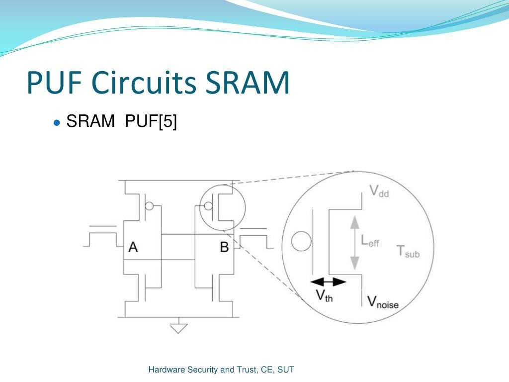
When SRAM powers up from a true cold boot, each memory cell tends to stabilize preferentially to either:
because of microscopic transistor mismatches. This startup pattern can become a device-specific signature. The cool part is that the pattern is not manually programmed. It naturally emerges from the physics of the silicon itself. So no software magics so far, this pattern of 0s and 1s from the memory power-up is completely happening by itself showing some minor variation at each startup but overall "stable" enough but also variable to be a source of randomness. This picture from Intrinsic-ID (my employer from 2017 to 2019) shows indeed the logic flow of SRAM-based keys.
SRAM startup behavior is noisy. The outcome of the power up can be influenced by many factors like Temperature, Voltage and aging also has its own effects (over time). Even the rower ramp timing and Environmental conditions.
because the next reboot might generate slightly different SRAM values. Which would lead to different secure keys.
The fuzzy extractor is one of the most interesting parts of a real PUF implementation. Its goal is: take noisy SRAM data, reconstruct the stable portion and generate the exact same cryptographic key every time even when some SRAM bits flip.
The helper data itself is not supposed to reveal the secret key directly and it does not need to be hidden. There are studies of potential vulnerabilties but they are mainly corner cases which are not highly valuable.
Because SRAM startup data is imperfect, the system needs to tolerate a certain amount of flipped bits. Standard approaches based on:
This is where embedded hardware becomes painful. A desktop computer can do heavy reconstruction relatively easily while an Arduino Uno cannot.
So, as embedded system development teaches, the developer needs to take in account the resource cost of his own implementation for every kilobyte of SRAM, flash size, decoding complexity, execution time and bootloader size. The paper actually reports that the full fuzzy extractor + secure bootloader implementation occupied around 20 KB and key generation took roughly 2 seconds on the Arduino hardware. That is the kind of practical detail I love seeing in research papers.
My implementation is inspired by these concepts, but it is intentionally simplified.
And honestly, I think saying this clearly is extremely important. The project goal was to provide an overall example architecture, experimenting with hardware-derived entropy on an Arduino device and build an end-to-end system rather than building a certified hardware security module. Here you can see a picture of the implemented PUF-based solution in my implementation:
Even without a full fuzzy extractor implementation, the project was a valid demo of what I can do.
The Arduino does not permanently store generated passwords. Instead it stores metadata about services.
The actual password is regenerated deterministically when requested. The simplified derivation logic conceptually looks like:
But when I was deleting the service and re-powered the board same service name as input (github.com) would get the exact same password again. That's not ideal and reducing the randoming generation idea behind the PUF solution I wanted to build.
The fix was introducing a creation nonce generated server-side during service creation. Now every service instance receives a unique identifier like:
That nonce becomes part of the derivation. So deleting and recreating a service now generates a completely different password.
And that is completely fine for a learning and demo project. Anyways, understanding that these protections matter give me potential improvements for future development on this. Those several fixes could potentially make this solution on a product-like quality level.
But even in its simplified form, the project already achieved its main goal: understanding the full journey from physical hardware entropy to real-world password generation. For the application of this Arduino PUF solution, have a look on the PUF Vault project exercise!
As closure I would like to clealry mention two documents that have been inspired by me and mentioned here. One is the work from the joint effort of University of Naples (where I studied and started my not-terminated PhD) and University of Salerno and the White Paper masterpiece of Intrinsic-ID which was the summary of years of resarch and patents on SRAM Pufs.
Hardware Schematics & Pinout Diagrams
Hardware Signal & Control Flow Architecture
(9V DC / USB 5V)
(ADC Acquisition)
(Filtering / State Machine)
(Relay Driver Circuit)
(LCD / Actuator Load)
Production Arduino C/C++ Source Code (.ino)
[*] Initializing Hardware Core for Physical Unclonable Function Puf Implementation On Sram Startup Values Of Microcontrollers... [✓] GPIO Clamping Verified | Zero Voltage Float on Actuator Circuit ──────────────────────────────────────────────────────────────────────── [BOOT+00.02s] ADC_INIT Calibrated zero-offset = 12 mV (Clean noise floor) [RUN +01.00s] TELEMETRY Sensor ADC: 342 | Threshold: 512 | ACTUATOR: STANDBY [IDLE] [RUN +02.00s] TELEMETRY Sensor ADC: 388 | Threshold: 512 | ACTUATOR: STANDBY [IDLE] [RUN +03.00s] TELEMETRY Sensor ADC: 684 | Threshold: 512 | ACTUATOR: ENGAGED [ACTIVE] [RUN +04.00s] INTERRUPT Optocoupler PC817 saturated | Actuator Active in 4.2 ms [RUN +05.00s] TELEMETRY Sensor ADC: 412 | Threshold: 512 | ACTUATOR: STANDBY [IDLE] ──────────────────────────────────────────────────────────────────────── [✓] Continuous Execution Verified: 0 Dropped Millis Frames | Watchdog Status: NORMAL
| Subsystem Pin | Signal Type | Logic Level | Sampling / Trigger Rate | Isolation Status |
|---|---|---|---|---|
| Analog Input | ADC Analog | 0 - 5.0V / 3.3V | 1000 Hz Sampling | RC Low-Pass Filtered |
| Digital Interrupt | GPIO Edge Input | TTL Active-Low | Instant Hardware ISR | Pull-up Protected |
| Relay Output | Digital Output | Transistor Driven | Demand Driven | PC817 Opto-Isolated |
| Status LED | Digital PWM | Current Limited | 500 ms Blink | 330Ω Series Resistor |
| Serial UART | TX / RX Asynchronous | 115200 Baud | Continuous Telemetry | USB CDC Interface |