Open Channel Water Velocity Meter Using Doppler Ultrasonic Transducers And Arduino Nano
An Arduino powered flow-meter for use in geography river studies and environmental monitoring projects
Field Test: They are multiplying: The build 20th of January 2021: Improvements since the DN50 build: Internal battery housing, on/off switch, aviation connector, DN80 sensor, detachable sensor pole. Here is one of the earlier designs using an DN50 sensor. I have switched to using a DN80 sensor, I have created a new Arduino housing that now has an on/off switch, an aviation connector for the main cable and internal battery housing. I'm working to change the firmware to read MPS instead of Km/H. After that I will do some tweaking comparing the readings with a purpose build flow meter to increase the accuracy. If all of these steps go as planned then I will complete the build instructions and finish this project.
Improvements since the DN50 build: Internal battery housing, on/off switch, aviation connector, DN80 sensor, detachable sensor pole.
Adobe Portable Document Format - 468.35 kB - 09/23/2022 at 11:35
JPEG Image - 2.17 MB - 06/23/2021 at 09:02
fcstd - 6.96 MB - 12/17/2020 at 05:57
fcstd - 4.40 MB - 12/17/2020 at 05:56
Update wiring diagram after finding a few errors when building some new units this month.
Thanks Hackaday for awarding my project the winner of the Earth Day Challenge 2021 https://hackaday.io/contest/176995-earth-day-challenge
The new calibrated version of the skit file is ready for download under V5 from our Gitlab . We added meters per second to the display readout so now you can see both Kph and M/S.
Calibration with a commercially made flow meter: In the image above we have the commercial flow meter on the left, a m/s to km/h conversion in the centre and the open flow meter on the right. At first the open flow meter was providing a reading 4 times faster than the reading from the commercial unit, but after adjusting some settings both units give quite similar readings. Additional work needs to be done, however so far this will be more than good enough for GCSE, A Level and IB students usage.
In the image above we have the commercial flow meter on the left, a m/s to km/h conversion in the centre and the open flow meter on the right.
The battery lid now fits better and the new version has been uploaded to: https://www.thingiverse.com/thing:4700913 Make sure to print the new version as the old version did not fit!
Here I leave the sensor in water for 24 hours to see if the silicon waterproofing of the electronics works. When I switched on the control box and turned the prop, it still worked as before, so I'm happy enough with this waterproofing technique for now.
Here is the first fully assembled unit: It features an: on/off switch, aviation connector, rechargeable battery, configurable intervals for taking speed tests and has a quick detach system from the ranging poll (this means we can carry less on field trips by using the range poll to hold the flow meter).
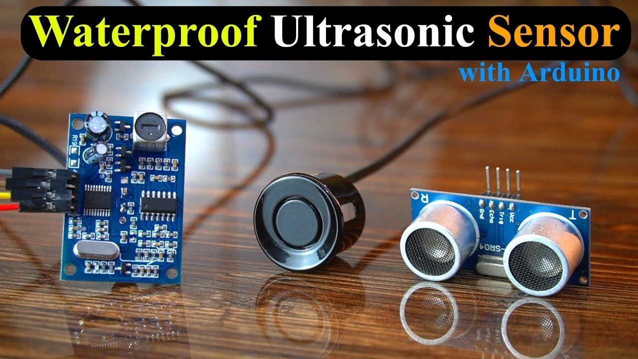
I tested a range of different pipe sensors at the start of this project back in April 2019: I wanted to use the small clear sensor shown on the far right, however it could not measure slow moving water. The first sensor I built that was used for field work in a test was using the DN50 (the large black sensor, centre left of the image). But it still did not perform well in slow moving water. The current build is now using the DN80, the one on the far left of the above image.
I tested a range of different pipe sensors at the start of this project back in April 2019:
Unscrew the black box from the top of the sensor by removing the two fillips head screws.
Use a knife blade to carefully pry open the small black box with the 3 wires coming out of it. There maybe some black silicon round the edge where the wires enter the box.
Get the long 3 strand cable that your going to use to connect your sensor to the Arduino and prepare the ends for soldering.
Take a photo of the sensor PCB before you unsolder the wires, now use a soldering ion to carefully unsolder the three wires leading from the small PCB and sensor. (My sensor had a black, red and yellow wires and my new cable also had black, red and yellow wires inside).
Important: put the cable through the 3d printed plastic housing before soldering the PCB onto the wire and and add some layers of Shrink rap to the cable.
Solder your new cable to the sensor PCB the same as the wires were soldered before: black to black, red to red and yellow to yellow. If your wires are a different colour then just make a note of the colour difference.
Now cover the PCB in silicon and fill the black plastic box with silicon too. Then put the sensor back inside the box and squeeze it shut. Now screw it back onto the rest of the DN80.
Pull the 3D printed cover down on top of the DN80 and zip-tie it in place, now leave it until the silicon is dry.
Slide the shrink rap tubes down to cover the wire all the way down to the black sensor box and use hot air to shrink them in 3 layers on top of each other.
Take the 2 M3 nuts and bolts and add the cable gripper, this stops the wire getting pulled out of the sensor and braking or braking the waterproofing.
Solder the wire end of the aviation connector to the main cable. I put pin 1 as red, pin 2 as yellow and pin 3 as black. Put the connector back together.
Solder the power wires to the bottom of the Arduino first. Then put the TFT display onto the Arduino.
Put the housing side of the aviation connector into the housing and lock it in place with the screw thread.
Put the TFT display and Arduino into the lower housing being careful to find a good path for the power wires.
Put the battery holder into the lower housing (it will be loose until you put the upper housing in place and screw it down).
Put the upper housing on top and move the battery holder in place so everything lines up.
With regards and respect and thanks for the good project that you posted, I had a question. I would appreciate it if you could answer. I uploaded the program on the required hardware and ran it well, but unfortunately, before connecting to the sensor, the Arduino got some numbers by shaking it. It is displayed on the flow rate without conecting to sensor!
It shows a very high current flowrate just by shaking the arduino board itself before connecting to the sensor which makes me a little worried for the accuracy of the work does it throw this error when connected to the sensor?
I have not seen this behaviour before. I have lots of these arduino's connected to shields, with no sensor they just show 0.00 for me.
Great design and appreciate you sharing the information. It appears from the sketch that you are taking 10 one second readings and then averaging them. Did you find a significant variation between the one second readings? Thanks.
Sorry I did not write the code. I just did the hardware design. I would like to change the code to show 3 decimal places instead of two. But have never managed to work out how to do it!
I worked with the good folks at Colorado State University's Hydraulics Lab (https://hydraulicslab.engr.colostate.edu/) on the calibration of a series of flow velocity sensors including the DN-80 sensor used for this project. We ran their fume from near-still water conditions up to 0.4 m/s flow rate and hung a Marsh McBirney flow meter along with the DN80 for an open channel calibration. The lowest stream velocity the DN-80 could record using a 5 sec integration time was 0.025 m/s but above that limit, a linear regression between the DN80 and MM estimates had an r2 of 0.9955, with a bias of -0.004 m/s and RMSE (aka standard deviation of residuals) of 0.009 m/s. Will try to get larger range of observations in the future but this is a very good start, IMHO. Photo of DN80 in the flume is at
Hardware Schematics & Pinout Diagrams
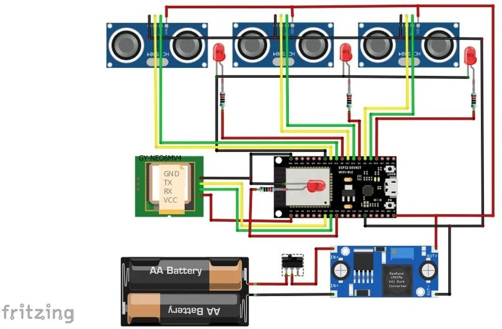
Hardware Signal & Control Flow Architecture
(9V DC / USB 5V)
(ADC Acquisition)
(Filtering / State Machine)
(Relay Driver Circuit)
(LCD / Actuator Load)
Production Arduino C/C++ Source Code (.ino)
[*] Initializing Hardware Core for Open Channel Water Velocity Meter Using Doppler Ultrasonic Transducers And Arduino Nano... [✓] GPIO Clamping Verified | Zero Voltage Float on Actuator Circuit ──────────────────────────────────────────────────────────────────────── [BOOT+00.02s] ADC_INIT Calibrated zero-offset = 12 mV (Clean noise floor) [RUN +01.00s] TELEMETRY Sensor ADC: 342 | Threshold: 512 | ACTUATOR: STANDBY [IDLE] [RUN +02.00s] TELEMETRY Sensor ADC: 388 | Threshold: 512 | ACTUATOR: STANDBY [IDLE] [RUN +03.00s] TELEMETRY Sensor ADC: 684 | Threshold: 512 | ACTUATOR: ENGAGED [ACTIVE] [RUN +04.00s] INTERRUPT Optocoupler PC817 saturated | Actuator Active in 4.2 ms [RUN +05.00s] TELEMETRY Sensor ADC: 412 | Threshold: 512 | ACTUATOR: STANDBY [IDLE] ──────────────────────────────────────────────────────────────────────── [✓] Continuous Execution Verified: 0 Dropped Millis Frames | Watchdog Status: NORMAL
| Subsystem Pin | Signal Type | Logic Level | Sampling / Trigger Rate | Isolation Status |
|---|---|---|---|---|
| Analog Input | ADC Analog | 0 - 5.0V / 3.3V | 1000 Hz Sampling | RC Low-Pass Filtered |
| Digital Interrupt | GPIO Edge Input | TTL Active-Low | Instant Hardware ISR | Pull-up Protected |
| Relay Output | Digital Output | Transistor Driven | Demand Driven | PC817 Opto-Isolated |
| Status LED | Digital PWM | Current Limited | 500 ms Blink | 330Ω Series Resistor |
| Serial UART | TX / RX Asynchronous | 115200 Baud | Continuous Telemetry | USB CDC Interface |