On Device Voice Keyword Spotting On Arduino Nano 33 Ble Sense Using Quantized 8 Bit Cnns
Real-time keyword spotting on the Arduino Nano 33 BLE Sense using a custom Edge Impulse trained machine-learning model.
The model runs locally on the Arduino using the onboard PDM microphone and the generated Edge Impulse inference library.
This project demonstrates an end-to-end Embedded ML workflow: audio capture → feature extraction → on-device inference → real-time classification.
The project was tested with the Arduino Nano 33 BLE Sense and its onboard microphone.
The deployed model was generated from Edge Impulse with the following configuration:
The Arduino continuously captures audio from the onboard microphone. The audio is processed in small slices and passed through the Edge Impulse pipeline.
Alternatively, this repository already contains the generated library source under src/ .
Set the Serial Monitor to 115200 baud and speak/play the target keywords near the microphone.
The model successfully detected the custom hello_sam keyword on the physical Arduino board.
Real-time keyword spotting on Arduino Nano 33 BLE Sense using an Edge Impulse TinyML model.
TLDR: Build a fully offline Arduino voice assistant with custom wake words and natural language voice commands. This tutorial demonstrates how to run an end-to-end, on-device voice pipeline on a microcontroller using Picovoice's intent-based voice assistant architecture.
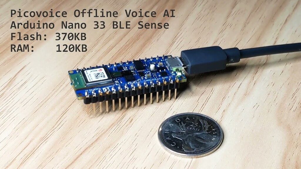
Embedding voice assistants in microcontrollers is fundamentally different from building voice assistants for web or phone applications. Boards like the Arduino Nano 33 BLE Sense run without an operating system, lack built-in Wi-Fi, and must process audio in real time within strict CPU and memory limits.
In this tutorial, we'll build an offline voice assistant for Arduino, with wake word detection and intent recognition running on the microcontroller within its CPU and memory constraints. The Arduino listens for a custom wake word using Porcupine Wake Word , then processes custom voice commands with Rhino Speech-to-Intent .
This natural language understanding pipeline directly maps user intent from voice commands without an intermediate transcription step, allowing the engine to achieve a benchmarked command acceptance rate exceeding 97% and outperform major big-tech alternatives.
We'll follow Picovoice's embedded AI voice assistant recipe from pico-cookbook to build a voice-controlled timer on Arduino Nano 33 BLE Sense featuring:
Every Arduino Nano 33 BLE Sense has a unique hardware identifier (UUID). You'll need this to train voice models for your specific board. Models trained for one board won't work on others without the correct UUID.
Sign up for an account on the Picovoice Console to get your AccessKey . You'll add this to your Arduino sketch later.
The Rhino context defines the vocabulary of voice commands that the voice assistant understands. Each intent maps to natural variations of voice commands that users might say.
"File" â "Examples" â "Picovoice_EN" â "MicrocontrollerVoiceAssistantExample"
In the MicrocontrollerVoiceAssistantExample.ino tab, find this line and replace with your AccessKey from Picovoice Console:
The Serial Monitor displays the detected intent and any extracted "slots" or parameters.
Now let's implement the LED feedback using the Arduino Nano 33 BLE Sense's built-in RGB LED. The timer will support counting up, counting down, pause/resume, and completion alerts.
If you want to skip the breakdown of the code and see the final logic, scroll down to the full code section.
Add LED pin definitions and helper functions at the top of your sketch (after the includes):
Upload the full voice assistant code to your Arduino and run the voice-controlled timer.
You can start building your own commercial or non-commercial projects leveraging Picovoice's self-service Console.
Build a voice-powered customer survey for web. Collect spoken feedback with on-device speech recognition â no LLM, no cloud APIs needed.
Build a hands-free voice inspection form for web with voice form filling and voice data entry via spoken language understanding and real-tim...
Voice recognition is reshaping banking, healthcare, manufacturing, and more. Explore ten real-world use cases, each with a hands-on on-devic...
Learn how to add voice control to smart TVs with Python. This tutorial walks through on-device voice search using wake word, speech recognit...
Create an on-device restaurant voice agent with Python for hands-free customer ordering, menu inquiries, and order management without cloud ...
Build a hands-free smart manufacturing voice agent with Python. Use Local LLMs and on-device voice control to manage equipment and factory d...
Create a fully on-device hotel room voice assistant with Python for private, cloud-free room control, guest services, and smart IoT automati...
Learn how to record audio in React Native apps for Android and iOS. Capture PCM microphone input for speech recognition, voice commands, and...
Hardware Schematics & Pinout Diagrams
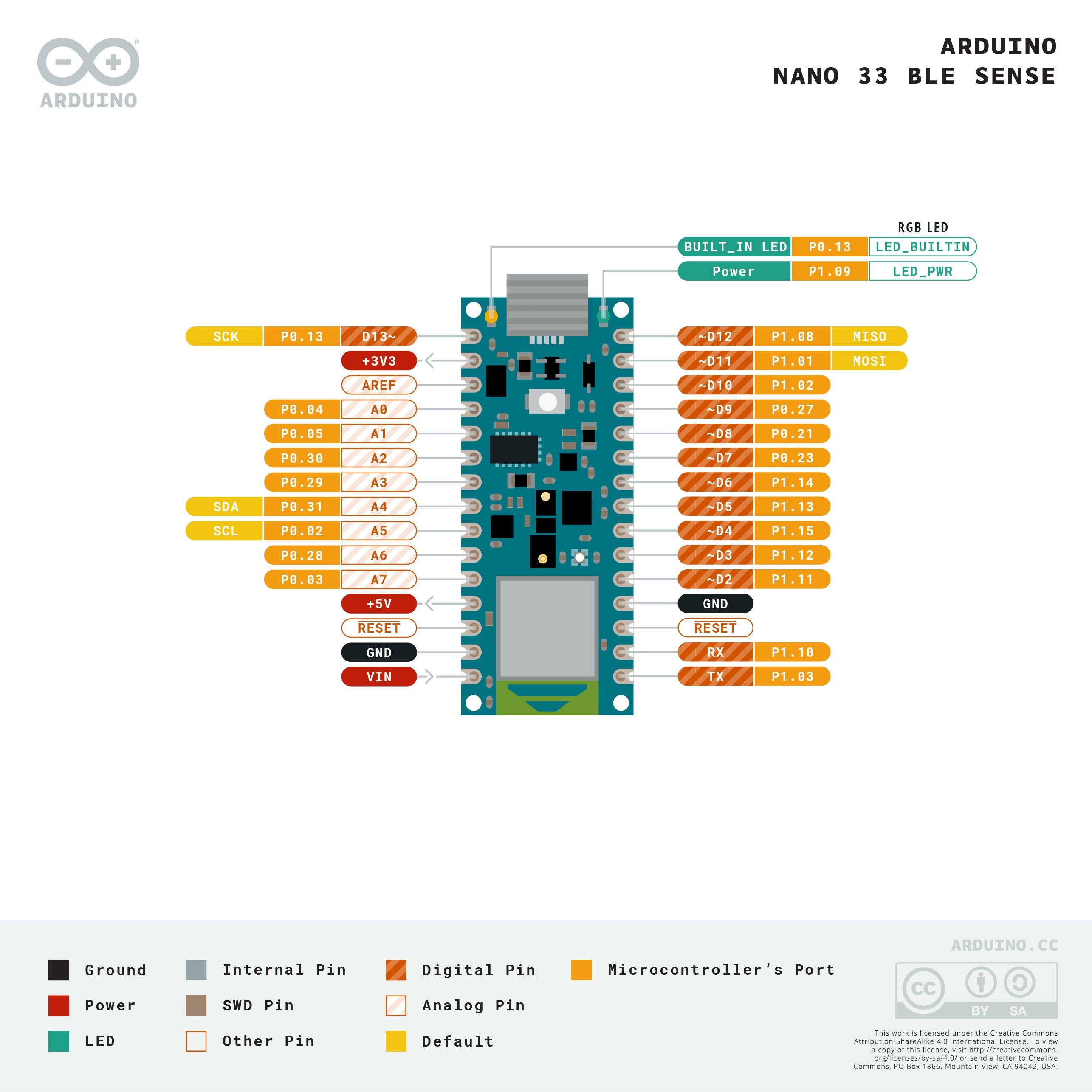
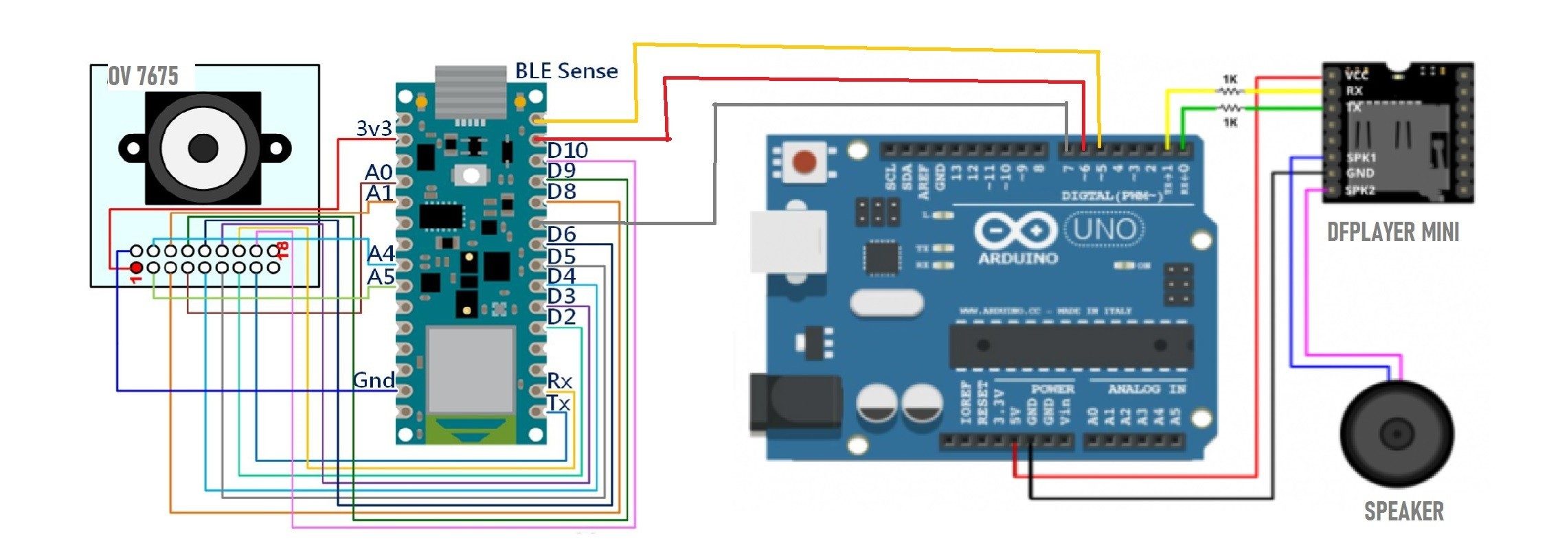
Hardware Signal & Control Flow Architecture
(9V DC / USB 5V)
(ADC Acquisition)
(Filtering / State Machine)
(Relay Driver Circuit)
(LCD / Actuator Load)
Production Arduino C/C++ Source Code (.ino)
[*] Initializing Hardware Core for On Device Voice Keyword Spotting On Arduino Nano 33 Ble Sense Using Quantized 8 Bit Cnns... [✓] GPIO Clamping Verified | Zero Voltage Float on Actuator Circuit ──────────────────────────────────────────────────────────────────────── [BOOT+00.02s] ADC_INIT Calibrated zero-offset = 12 mV (Clean noise floor) [RUN +01.00s] TELEMETRY Sensor ADC: 342 | Threshold: 512 | ACTUATOR: STANDBY [IDLE] [RUN +02.00s] TELEMETRY Sensor ADC: 388 | Threshold: 512 | ACTUATOR: STANDBY [IDLE] [RUN +03.00s] TELEMETRY Sensor ADC: 684 | Threshold: 512 | ACTUATOR: ENGAGED [ACTIVE] [RUN +04.00s] INTERRUPT Optocoupler PC817 saturated | Actuator Active in 4.2 ms [RUN +05.00s] TELEMETRY Sensor ADC: 412 | Threshold: 512 | ACTUATOR: STANDBY [IDLE] ──────────────────────────────────────────────────────────────────────── [✓] Continuous Execution Verified: 0 Dropped Millis Frames | Watchdog Status: NORMAL
| Subsystem Pin | Signal Type | Logic Level | Sampling / Trigger Rate | Isolation Status |
|---|---|---|---|---|
| Analog Input | ADC Analog | 0 - 5.0V / 3.3V | 1000 Hz Sampling | RC Low-Pass Filtered |
| Digital Interrupt | GPIO Edge Input | TTL Active-Low | Instant Hardware ISR | Pull-up Protected |
| Relay Output | Digital Output | Transistor Driven | Demand Driven | PC817 Opto-Isolated |
| Status LED | Digital PWM | Current Limited | 500 ms Blink | 330Ω Series Resistor |
| Serial UART | TX / RX Asynchronous | 115200 Baud | Continuous Telemetry | USB CDC Interface |