Municipal Sewer Gas Toxic Overload Detector H2s
This a simple setup that can be built using a microcontroller, sensor and a display. For my version I have used:
This Arduino code allows the Arduino to receive data from MCQ136 at one second intervals and display it on the OLED.
The H2S Sensor (SEN0568) by DFRobot is a high-performance device designed to detect the presence of hydrogen sulfide (H2S) gas in the environment. Hydrogen sulfide is a toxic and flammable gas commonly found in industrial settings, making this sensor an essential tool for safety monitoring and environmental analysis. The sensor provides reliable and accurate measurements, ensuring timely detection of H2S gas to prevent hazardous situations.
This circuit is designed for environmental monitoring, specifically for detecting harmful algal blooms (HABs) by measuring pH, turbidity, and temperature. It uses an Arduino Nano interfaced with a pH meter, turbidity module, and DS18B20 temperature sensor to collect data, and a SIM900A GSM module to send SMS alerts when the readings exceed predefined thresholds. The circuit also includes an LCD screen for displaying the measurements and a resistor for the temperature sensor setup.
This circuit is designed for environmental monitoring, utilizing an ESP32 microcontroller to collect data from various sensors including an MQ-136 for H2S detection, an SCD30 for CO2 and humidity measurement, and an SJH-100A for methane detection. The collected data is processed and can be integrated with Home Assistant for real-time monitoring and analysis.
This circuit is a multi-sensor environmental monitoring system using an Arduino Mega 2560. It measures temperature, methane, CO2, pH, and TDS levels, displaying the data on an LCD and controlling a relay based on temperature thresholds. The system also includes Bluetooth communication for data transmission.
This circuit is designed to measure pH and TDS (Total Dissolved Solids) levels in a solution using a pH sensor and a TDS sensor, respectively, interfaced with an Arduino Leonardo. The measured data is then displayed on a 0.96" OLED screen.
The following table outlines the key technical details of the H2S Sensor (SEN0568):
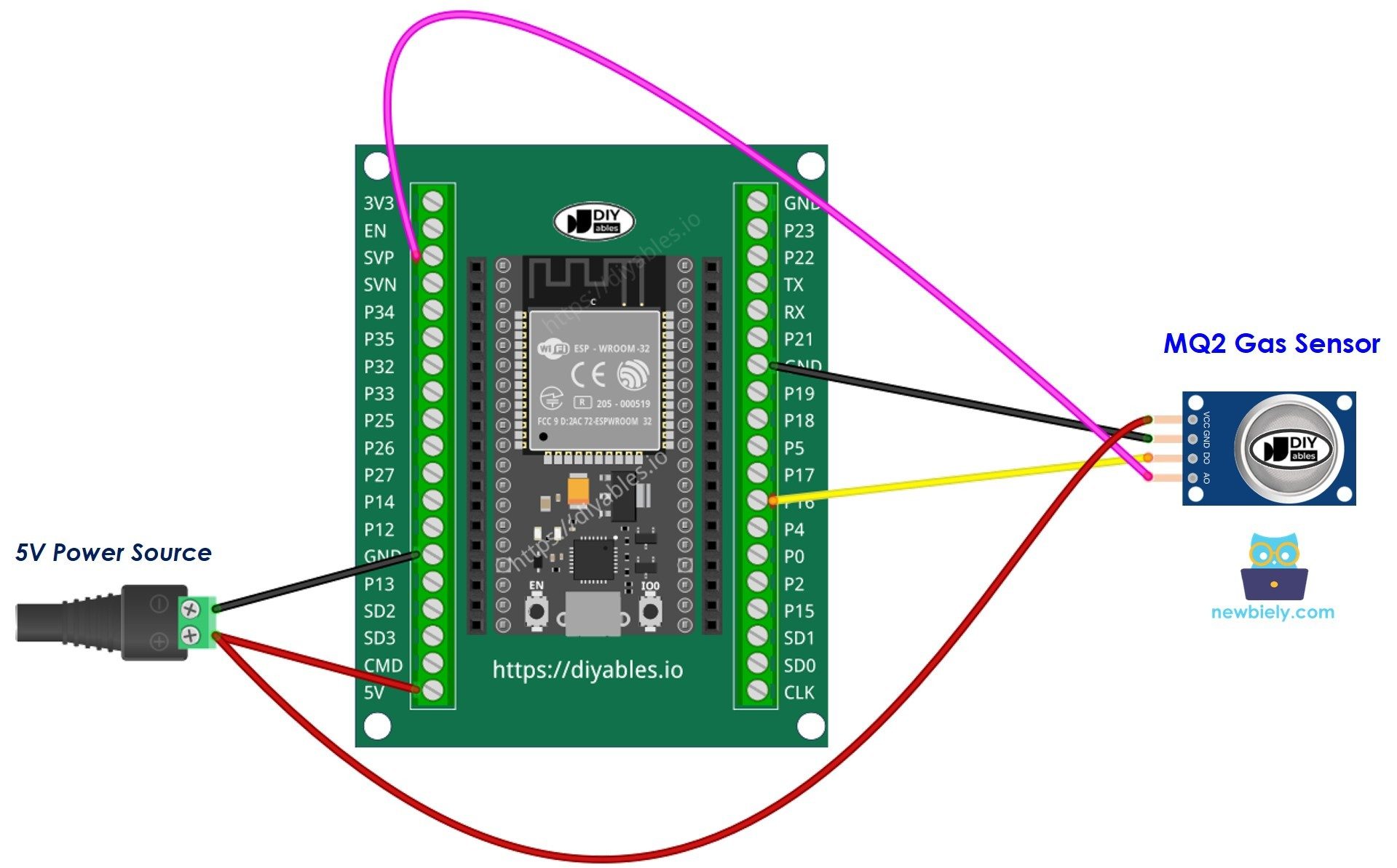
The H2S Sensor (SEN0568) has a simple pinout for easy integration into circuits. The pin configuration is as follows:
Below is an example code to interface the H2S Sensor (SEN0568) with an Arduino UNO:
Q1: Can the sensor detect gases other than H2S? A1: No, the sensor is specifically designed to detect hydrogen sulfide (H2S) gas and may not provide accurate readings for other gases.
Q2: How often should the sensor be calibrated? A2: The sensor should be calibrated periodically, depending on the application and environmental conditions. Refer to the manufacturer's guidelines for calibration intervals.
Q3: Can the sensor be used outdoors? A3: Yes, but ensure it is protected from direct exposure to rain, extreme humidity, and dust to maintain accuracy and longevity.
Q4: What is the lifespan of the sensor? A4: The sensor's lifespan depends on usage and environmental conditions. Under normal conditions, it can last several years with proper care and maintenance.
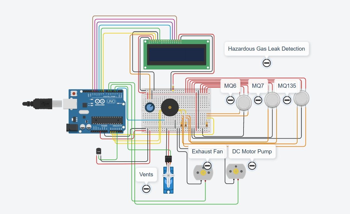
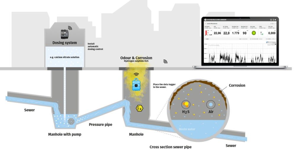
This project is a safety system I developed to detect harmful gases in sewer pits and alert sanitation workers using voice messages.
An Arduino-based safety system for detecting hazardous gases in sewers to protect worker health and safety.
When Hazardous Gas detect then a warning is displayed on LCD and automatic air tight doors are locked to control emissions of hazardous gases.
Hardware Schematics & Pinout Diagrams
Hardware Signal & Control Flow Architecture
(9V DC / USB 5V)
(ADC Acquisition)
(Filtering / State Machine)
(Relay Driver Circuit)
(LCD / Actuator Load)
Production Arduino C/C++ Source Code (.ino)
[*] Initializing Hardware Core for Municipal Sewer Gas Toxic Overload Detector H2s... [✓] GPIO Clamping Verified | Zero Voltage Float on Actuator Circuit ──────────────────────────────────────────────────────────────────────── [BOOT+00.02s] ADC_INIT Calibrated zero-offset = 12 mV (Clean noise floor) [RUN +01.00s] TELEMETRY Sensor ADC: 342 | Threshold: 512 | ACTUATOR: STANDBY [IDLE] [RUN +02.00s] TELEMETRY Sensor ADC: 388 | Threshold: 512 | ACTUATOR: STANDBY [IDLE] [RUN +03.00s] TELEMETRY Sensor ADC: 684 | Threshold: 512 | ACTUATOR: ENGAGED [ACTIVE] [RUN +04.00s] INTERRUPT Optocoupler PC817 saturated | Actuator Active in 4.2 ms [RUN +05.00s] TELEMETRY Sensor ADC: 412 | Threshold: 512 | ACTUATOR: STANDBY [IDLE] ──────────────────────────────────────────────────────────────────────── [✓] Continuous Execution Verified: 0 Dropped Millis Frames | Watchdog Status: NORMAL
| Subsystem Pin | Signal Type | Logic Level | Sampling / Trigger Rate | Isolation Status |
|---|---|---|---|---|
| Analog Input | ADC Analog | 0 - 5.0V / 3.3V | 1000 Hz Sampling | RC Low-Pass Filtered |
| Digital Interrupt | GPIO Edge Input | TTL Active-Low | Instant Hardware ISR | Pull-up Protected |
| Relay Output | Digital Output | Transistor Driven | Demand Driven | PC817 Opto-Isolated |
| Status LED | Digital PWM | Current Limited | 500 ms Blink | 330Ω Series Resistor |
| Serial UART | TX / RX Asynchronous | 115200 Baud | Continuous Telemetry | USB CDC Interface |