Multi Source Micro Energy Harvesting Combiner Managing Solar
Arduino-based Energy Harvesting System generating electrical energy from human motion for portable and smart power applications.
Md Istaque Ansari B.Tech Electronics & Communication Engineering Student Embedded Systems & Arduino Project Developer focused on practical, real-world engineering solutions. Actively building industry-ready technical skills and seeking opportunities to contribute in innovative engineering and technology projects.
A practical Arduino-based Energy Harvesting System converting human motion into electrical energy, demonstrating embedded systems design, power management, and real-world hardware implementation for sustainable and portable energy applications.
An Arduino-based solar energy microgrid system with manual and automatic grid selection. The system switches between solar and utility power using relays based on voltage availability. Developed as an academic project.
This project implements a solar energy microgrid system that allows switching between solar power and utility grid power. The system supports both manual and automatic modes using switches and an Arduino controller.
Small and rural communities frequently experience unreliable electricity supply, with power outages lasting up to 7–8 hours a day. These frequent interruptions disrupt daily life, education, small businesses, and essential services, creating a significant challenge in maintaining a consistent and dependable power supply.
The system switches between solar and utility power using relays based on current availability.
In remote areas, off-grid, and energy-optimization-required scenarios, solar energy can be applied for powering. A smart solar microgrid management system using Arduino Uno to collect, manage, and distribute energy can pave the way for home and commercial-use solar energy systems. When you finish the design, you can have the solar energy system manufactured into real products through PCB assembly services .
This project presents a compact, cost-effective microgrid controller built around an Arduino Uno. It automatically manages three power sources: solar panels, a battery bank, and grid backup, and two types of loads (DC and AC).
By measuring voltage and current at key points, the system continuously computes power flows, prioritizes solar energy, charges the battery with surplus photovoltaics, and protects against over‑discharge. An optional Wi‑Fi module enables remote monitoring, while an LCD offers on-site feedback.
// initialize the LCD library with the numbers of the interface pins LiquidCrystal lcd(12, 11, 10, 9, 8, 7);
//-------------------------------------- VOLTAGE SENSORS const int Solar_Sen_Pin = A0; const int Grid_Sen_Pin = A1; const int Battery_Sen_Pin = A2;
//-------------------------------------- RELAYS const int Relay_Solar = A8; const int Relay_Grid = A9; const int Relay_Gnd = A10; const int Relay_Battery = A11; const int Relay_BatteryN = A12; const int Relay_High = A13; const int Relay_Normal = A14; const int Relay_Low = A15;
//-------------------------------------- BUTTONS const int Button_PH = 2; const int Button_B40 = 3; const int Button_High = 4; const int Button_Normal = 5; const int Button_Low = 6;
int ButtonState_PH; int ButtonState_B40; int ButtonState_High; int ButtonState_Normal; int ButtonState_Low;
void setup { Serial.begin(9600); // LCD init lcd.begin(20, 4); lcd.clear; lcd.setCursor(0, 0); lcd.print("SMART HYBRID"); lcd.setCursor(0, 1); lcd.print("ENERGY MANAGEMENT"); lcd.setCursor(0, 2); lcd.print("SYSTEM USING"); lcd.setCursor(0, 3); lcd.print("ARDUINO"); delay(5000); lcd.clear; lcd.setCursor(0, 0); lcd.print("DESIGNED BY:"); lcd.setCursor(0, 1); lcd.print("ASFANDIYAR TARIQ"); lcd.setCursor(0, 2); lcd.print("AND"); lcd.setCursor(0, 3); lcd.print("SAAD KHAN"); delay(5000); lcd.clear;
// Sensor pins pinMode(Solar_Sen_Pin, INPUT); pinMode(Grid_Sen_Pin, INPUT); pinMode(Battery_Sen_Pin, INPUT);
// Relay pins pinMode(Relay_Solar, OUTPUT); pinMode(Relay_Grid, OUTPUT); pinMode(Relay_Gnd, OUTPUT); pinMode(Relay_Battery, OUTPUT); pinMode(Relay_BatteryN, OUTPUT); pinMode(Relay_High, OUTPUT); pinMode(Relay_Normal, OUTPUT); pinMode(Relay_Low, OUTPUT);
digitalWrite(Relay_Solar, HIGH); digitalWrite(Relay_Grid, HIGH); digitalWrite(Relay_Gnd, HIGH); digitalWrite(Relay_Battery, HIGH); digitalWrite(Relay_BatteryN, HIGH); digitalWrite(Relay_High, HIGH); digitalWrite(Relay_Normal, HIGH); digitalWrite(Relay_Low, HIGH);
// Button pins pinMode(Button_PH, INPUT_PULLUP); pinMode(Button_B40, INPUT_PULLUP); pinMode(Button_High, INPUT_PULLUP); pinMode(Button_Normal, INPUT_PULLUP); pinMode(Button_Low, INPUT_PULLUP);
// Bluetooth init (only warning for Uno) #if defined(USART1_RX_vect) || defined(UBRR1H) Serial1.begin(9600); #else Serial.println("Warning: Serial1 not supported on this board."); #endif }
void loop { #if defined(USART1_RX_vect) || defined(UBRR1H) if (Serial1.available > 0) { Blue_Val = Serial1.read; Serial.println(Blue_Val); } #endif
//-------------------------------------- Read voltage sensor values Solar_Val = analogRead(Solar_Sen_Pin); Grid_Val = analogRead(Grid_Sen_Pin); Battery_Val = analogRead(Battery_Sen_Pin);
// Assuming 11:1 voltage divider Solar_Volts = (Solar_Val * 5.0 / 1023.0) * 11.0; Grid_Volts = (Grid_Val * 5.0 / 1023.0) * 11.0; Battery_Volts = (Battery_Val * 5.0 / 1023.0) * 11.0;
//-------------------------------------- Read button states ButtonState_PH = digitalRead(Button_PH); ButtonState_B40 = digitalRead(Button_B40); ButtonState_High = digitalRead(Button_High); ButtonState_Normal = digitalRead(Button_Normal); ButtonState_Low = digitalRead(Button_Low);
//-------------------------------------- Debug prints Serial.print("Solar Volts: "); Serial.println(Solar_Volts); Serial.print("Grid Volts: "); Serial.println(Grid_Volts); Serial.print("Battery Volts: "); Serial.println(Battery_Volts);
//-------------------------------------- Display source availability lcd.setCursor(0, 0); if (Solar_Volts >= 2) lcd.print("S: ON "); else lcd.print("S:OFF "); lcd.setCursor(7, 0); if (Grid_Volts >= 2) lcd.print("G: ON "); else lcd.print("G:OFF "); lcd.setCursor(14, 0); if (Battery_Volts >= 2) lcd.print("B: ON "); else lcd.print("B:OFF ");
//-------------------------------------- Handle different conditions if (Solar_Volts >= 2 && Grid_Volts >= 2 && Battery_Volts >= 2) { lcd.setCursor(0, 1); lcd.print("SYSTEM: SOLAR "); digitalWrite(Relay_Solar, LOW); digitalWrite(Relay_Gnd, LOW); digitalWrite(Relay_Grid, HIGH); digitalWrite(Relay_Battery, HIGH); digitalWrite(Relay_BatteryN, HIGH); } else if (Solar_Volts < 2 && Grid_Volts >= 2 && Battery_Volts >= 2) { lcd.setCursor(0, 1); lcd.print("SYSTEM: GRID "); digitalWrite(Relay_Grid, LOW); digitalWrite(Relay_Gnd, LOW); digitalWrite(Relay_Solar, HIGH); digitalWrite(Relay_Battery, HIGH); digitalWrite(Relay_BatteryN, HIGH); } else if (Solar_Volts < 2 && Grid_Volts < 2 && Battery_Volts >= 2) { lcd.setCursor(0, 1); lcd.print("SYSTEM: BATTERY "); digitalWrite(Relay_Battery, LOW); digitalWrite(Relay_BatteryN, LOW); digitalWrite(Relay_Grid, HIGH); digitalWrite(Relay_Solar, HIGH); digitalWrite(Relay_Gnd, HIGH); } else if (Solar_Volts >= 2 && Grid_Volts < 2 && Battery_Volts >= 2) { lcd.setCursor(0, 1); lcd.print("SYSTEM: SOLAR "); digitalWrite(Relay_Solar, LOW); digitalWrite(Relay_Gnd, LOW); digitalWrite(Relay_Grid, HIGH); digitalWrite(Relay_Battery, HIGH); digitalWrite(Relay_BatteryN, HIGH); } else if (Solar_Volts < 2 && Grid_Volts < 2 && Battery_Volts < 2) { lcd.clear; lcd.setCursor(0, 0); lcd.print("NO SOURCE AVAILABLE"); digitalWrite(Relay_Solar, HIGH); digitalWrite(Relay_Grid, HIGH); digitalWrite(Relay_Battery, HIGH); digitalWrite(Relay_BatteryN, HIGH); digitalWrite(Relay_Gnd, HIGH); return; }
//-------------------------------------- Output Mode Control if (Blue_Val == '9') { digitalWrite(Relay_High, LOW); digitalWrite(Relay_Normal, LOW); digitalWrite(Relay_Low, LOW); } else if (Blue_Val == 'I') { digitalWrite(Relay_High, HIGH); digitalWrite(Relay_Normal, HIGH); digitalWrite(Relay_Low, HIGH); } else { if (ButtonState_High == 0 || Blue_Val == '1') { digitalWrite(Relay_High, LOW); digitalWrite(Relay_Normal, HIGH); digitalWrite(Relay_Low, HIGH); } else if (ButtonState_Normal == 0 || Blue_Val == '2') { digitalWrite(Relay_High, HIGH); digitalWrite(Relay_Normal, LOW); digitalWrite(Relay_Low, HIGH); } else if (ButtonState_Low == 0 || Blue_Val == '3') { digitalWrite(Relay_High, HIGH); digitalWrite(Relay_Normal, HIGH); digitalWrite(Relay_Low, LOW); } else { digitalWrite(Relay_High, HIGH); digitalWrite(Relay_Normal, HIGH); digitalWrite(Relay_Low, HIGH); } }
//-------------------------------------- Additional display info lcd.setCursor(0, 2); if (ButtonState_PH == 0) lcd.print("Peak Hours: YES "); else lcd.print("Peak Hours: NO ");
lcd.setCursor(0, 3); if (ButtonState_B40 == 0) lcd.print("Battery < 40% "); else lcd.print("Battery > 40% ");
Once your ESP and APK speak the same language, the app will display real-time microgrid telemetry with no extra coding on your part.
OEM original equipment manufacturing services include prototypes, PCB printed circuit board fabrication, component sourcing, PCB assembly, enclosures, box-build assembly, burn-in, IC programming, functional testing, and other value-added services. To have your solar energy systems or equipment manufactured from scratch to finished products under one roof, partner with the OEM PCBA manufacturer PCBONLINE .
Founded in 1999, the OEM PCB manufacturer, PCBONLINE, has two large advanced PCB manufacturing bases independently fabricating all types of PCBs, one EMS (electronic manufacturing service) PCB assembly factory with two component warehouses, stable supply chains, and an R&D team. Besides, it keeps long-term cooperation with the top 3 mold/enclosure manufacturers in China to provide the molds, jigs, and enclosures for full box-build solutions.
PCBONLINE has rich R&D experience for solar energy systems, such as battery management systems, cell contact systems, enclosure designs, etc.
Turnkey PCB manufacturing and assembly for solar energy systems from prototypes to bulk production.
Our experienced R&D and engineering teams provide one-on-one support, solving technical and non-technical challenges while offering optimization suggestions to ensure your project runs smoothly from start to finish.
High-quality PCBA manufacturing certified with ISO 9001:2015, ISO 14001:2015, IATF 16949:2016, RoHS, REACH, UL, and IPC-A-610 Class 2/3.
When your project enters the bulky production stage, PCBONLINE refunds the fees of prototyping, including its value-added services.
No matter what quantity of boards you order, PCBONLINE prioritizes quality. To get a quote from the OEM PCBA manufacturer PCBONLINE, contact info@pcbonline.com .
The smart solar microgrid management system project in this article uses an Arduino Uno and simple sensors. It only provides the example codes without the schematics, so if you need R&D and OEM manufacturing, partner with the OEM PCBA manufacturer, PCBONLINE. By partnering with PCBONLINE, you can safely and successfully turn standalone solar and battery hardware into a self‑regulating microgrid, maximizing solar usage, safeguarding your battery, and keeping your solar energy product running smoothly.
PCBONLINE® is a registered trademark or service mark of pcb online limited or its affiliates.
Hardware Schematics & Pinout Diagrams
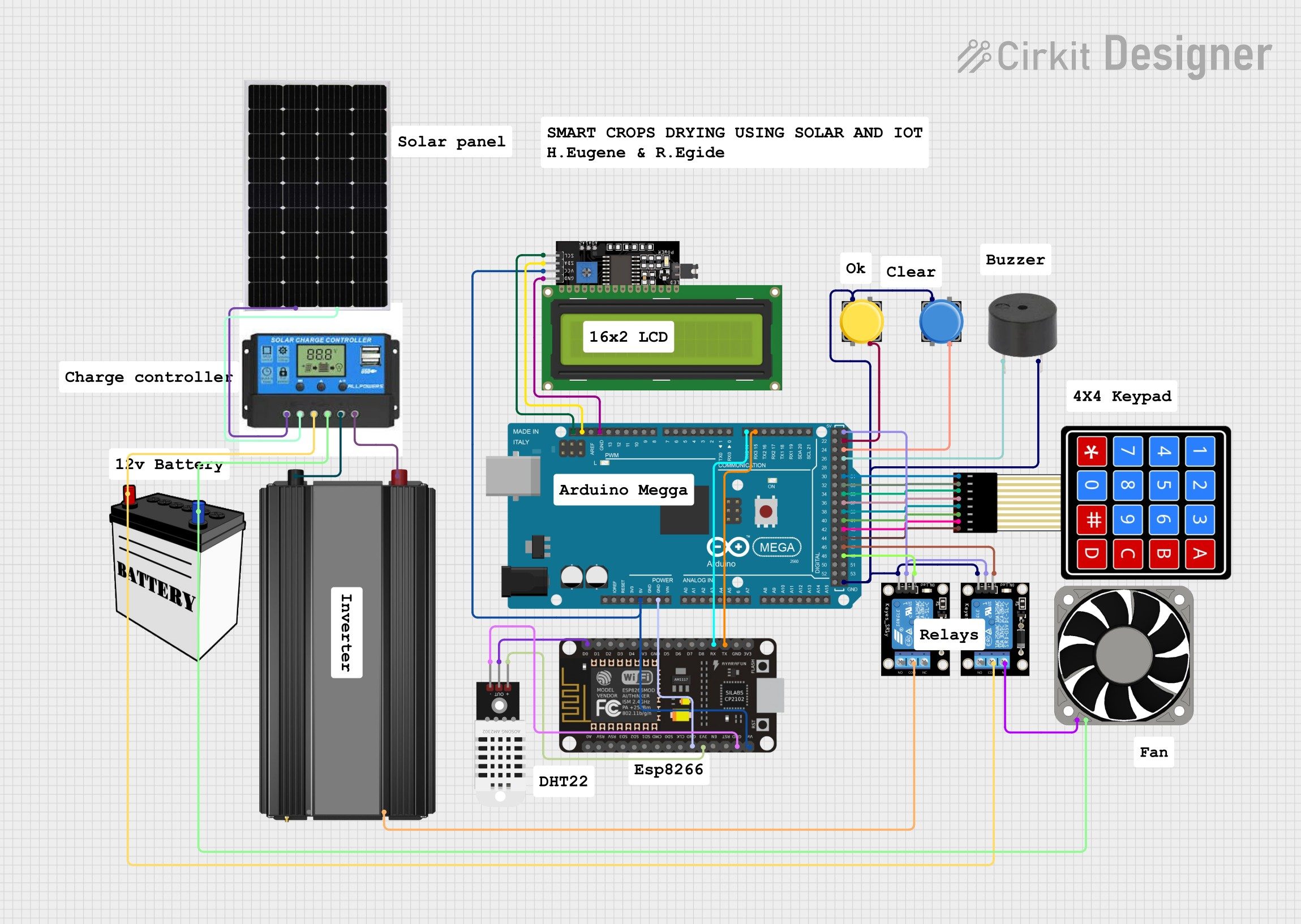
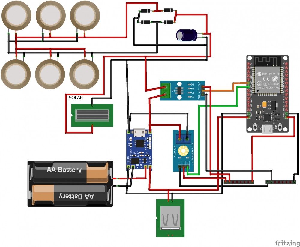
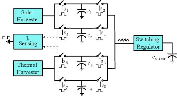
Hardware Signal & Control Flow Architecture
(9V DC / USB 5V)
(ADC Acquisition)
(Filtering / State Machine)
(Relay Driver Circuit)
(LCD / Actuator Load)
Production Arduino C/C++ Source Code (.ino)
[*] Initializing Hardware Core for Multi Source Micro Energy Harvesting Combiner Managing Solar... [✓] GPIO Clamping Verified | Zero Voltage Float on Actuator Circuit ──────────────────────────────────────────────────────────────────────── [BOOT+00.02s] ADC_INIT Calibrated zero-offset = 12 mV (Clean noise floor) [RUN +01.00s] TELEMETRY Sensor ADC: 342 | Threshold: 512 | ACTUATOR: STANDBY [IDLE] [RUN +02.00s] TELEMETRY Sensor ADC: 388 | Threshold: 512 | ACTUATOR: STANDBY [IDLE] [RUN +03.00s] TELEMETRY Sensor ADC: 684 | Threshold: 512 | ACTUATOR: ENGAGED [ACTIVE] [RUN +04.00s] INTERRUPT Optocoupler PC817 saturated | Actuator Active in 4.2 ms [RUN +05.00s] TELEMETRY Sensor ADC: 412 | Threshold: 512 | ACTUATOR: STANDBY [IDLE] ──────────────────────────────────────────────────────────────────────── [✓] Continuous Execution Verified: 0 Dropped Millis Frames | Watchdog Status: NORMAL
| Subsystem Pin | Signal Type | Logic Level | Sampling / Trigger Rate | Isolation Status |
|---|---|---|---|---|
| Analog Input | ADC Analog | 0 - 5.0V / 3.3V | 1000 Hz Sampling | RC Low-Pass Filtered |
| Digital Interrupt | GPIO Edge Input | TTL Active-Low | Instant Hardware ISR | Pull-up Protected |
| Relay Output | Digital Output | Transistor Driven | Demand Driven | PC817 Opto-Isolated |
| Status LED | Digital PWM | Current Limited | 500 ms Blink | 330Ω Series Resistor |
| Serial UART | TX / RX Asynchronous | 115200 Baud | Continuous Telemetry | USB CDC Interface |