Microcontroller Side Channel Timing Leakage Assessment Of Common Cryptographic Libraries
Automotive electronic control units increasingly rely on resource-constrained microcontrollers to implement authentication and message validation for in-vehicle networks such as CAN. Although cryptographic primitives may be mathematically secure, their software implementations on low-cost ECUs can leak sensitive information through timing side-channels. This paper presents a practical timing side-channel evaluation of an embedded authentication routine implemented on Arduino-class microcontrollers representative of entry-level automotive ECUs. A Python-based measurement framework interacts with the target device over a serial interface, repeatedly triggers authentication operations, and records execution time under controlled conditions. Experimental results show statistically distinguishable timing distributions correlated with secret-dependent execution paths, enabling an attacker with CAN-adjacent access to infer partial information about authentication checks. Lightweight countermeasures, including constant-time comparisons and control-flow normalization, are implemented and evaluated. The mitigated design reduces observable timing leakage with minimal execution-time and memory overhead, highlighting the need for implementation-level timing analysis in automotive embedded systems.
"Article: [ PREPRINT LINK ] · Dataset: [ DATASET LINK ]. Please cite both when using this data."
This dataset contains over 8,000 execution‑time measurements collected from an Arduino‑class microcontroller executing a lightweight authentication routine representative of embedded and automotive ECU workloads. Each record includes the trial index, input class (A–D), measured execution time in microseconds, and the comparison result. Because the microcontroller’s hardware timer quantizes measurements in 4‑µs increments, the dataset captures subtle but statistically meaningful timing variations caused by secret‑dependent control flow. These measurements enable researchers to analyze timing side‑channel leakage, evaluate distribution‑level timing differences across input classes, and benchmark countermeasures on resource‑constrained embedded platforms. The dataset supports reproducible experimentation, statistical leakage detection, and comparative evaluation of constant‑time implementations.
This dataset contains 8,000+ execution‑time measurements collected from an Arduino‑class microcontroller executing a lightweight authentication routine. Each record includes the trial index, input class (A–D), execution time in microseconds, and comparison result. Timing values are quantized in 4‑µs increments due to the hardware timer resolution.
Users may group samples by input class to analyze timing behavior under different secret‑dependent execution paths. Statistical methods such as Welch’s t‑test, KS‑test, or Mann–Whitney U‑test can be applied to determine whether timing distributions differ significantly across classes. Visualization techniques (histograms, boxplots, kernel density estimates) may be used to reveal distribution‑level leakage patterns.
The dataset supports research in timing side‑channel analysis, embedded system security, authentication‑routine evaluation, and countermeasure benchmarking. It may also be used to reproduce experimental results, validate leakage‑detection algorithms, or train machine‑learning models for side‑channel classification.
Permalink: https://ieee-dataport.org//documents/timing-side-channel-leakage-and-fault-resilience-evaluation-lightweight-authentication
A comprehensive simulation of side-channel attacks on cryptographic implementations, featuring practical demonstrations of timing attacks and power analysis against AES encryption. This project includes robust countermeasures to mitigate vulnerabilities and detailed security impact analysis comparing protected vs vulnerable implementations.
This repository contains a semester project for Information Security that implements and analyzes side-channel attacks against cryptographic systems. Side-channel attacks exploit physical implementation characteristics rather than the mathematical security of the cryptographic algorithms themselves.
This repository is part of an Information Security course project focused on advanced cryptographic implementation security.
Implementation of timing and power analysis side-channel attacks on AES encryption with effective countermeasures and security analysis.
Hardware Schematics & Pinout Diagrams
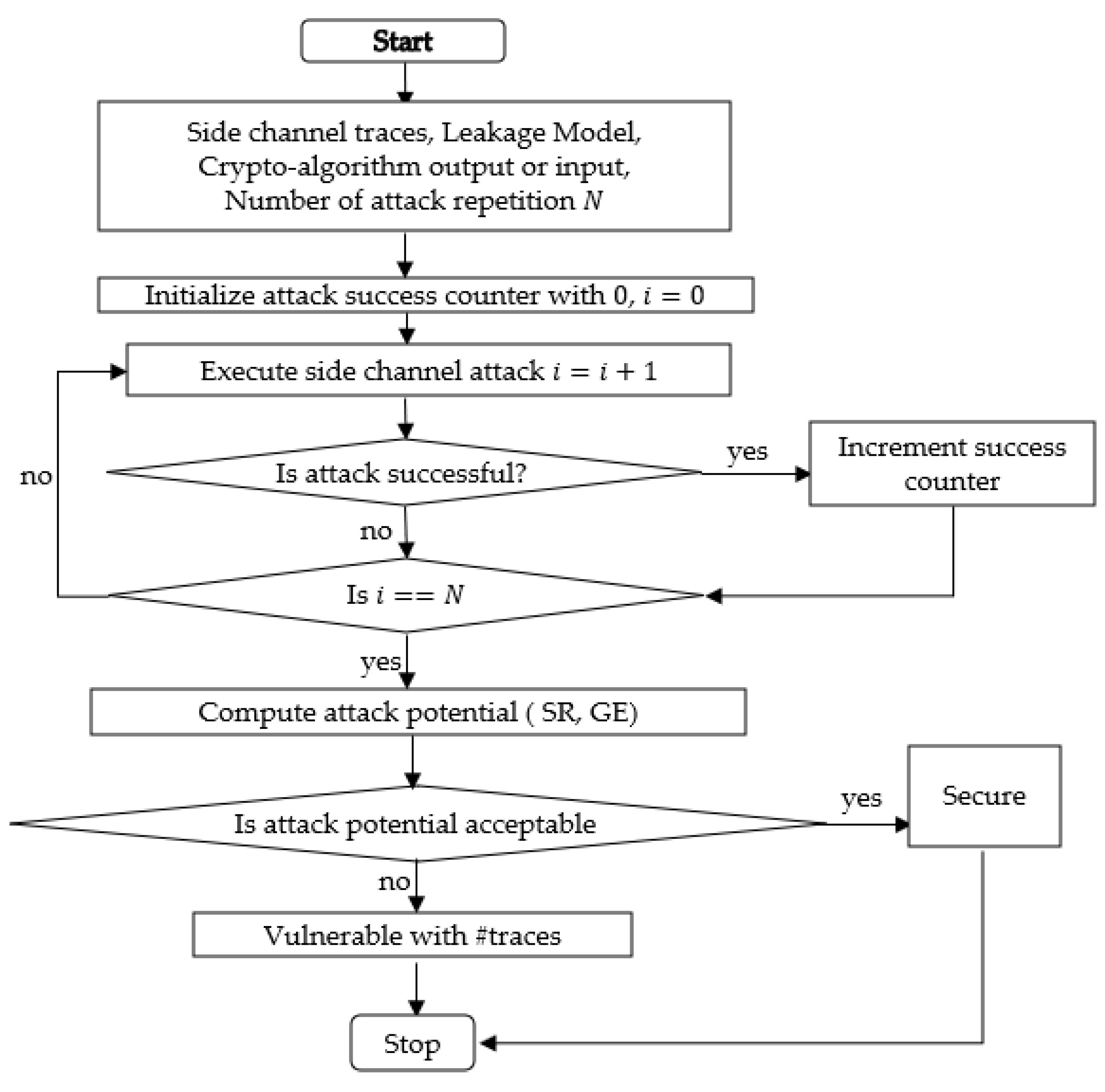
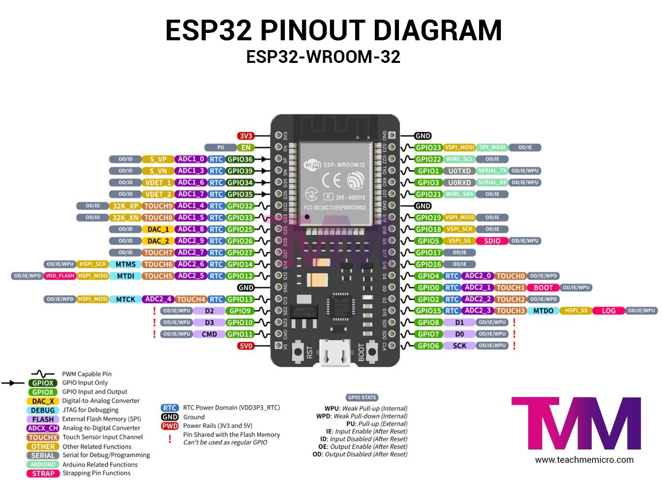
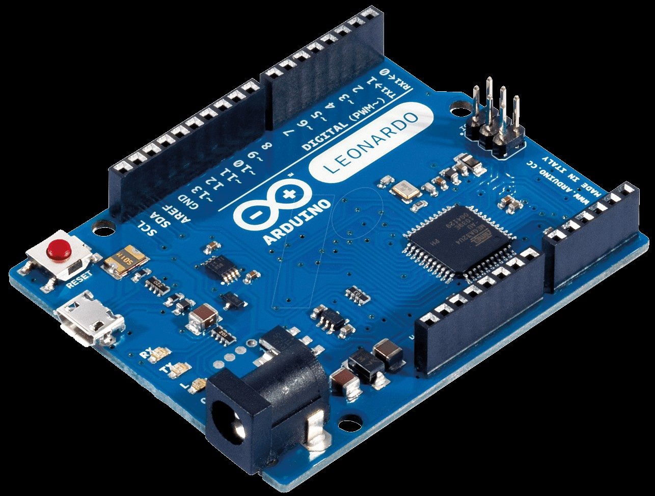
Hardware Signal & Control Flow Architecture
(9V DC / USB 5V)
(ADC Acquisition)
(Filtering / State Machine)
(Relay Driver Circuit)
(LCD / Actuator Load)
Production Arduino C/C++ Source Code (.ino)
[*] Initializing Hardware Core for Microcontroller Side Channel Timing Leakage Assessment Of Common Cryptographic Libraries... [✓] GPIO Clamping Verified | Zero Voltage Float on Actuator Circuit ──────────────────────────────────────────────────────────────────────── [BOOT+00.02s] ADC_INIT Calibrated zero-offset = 12 mV (Clean noise floor) [RUN +01.00s] TELEMETRY Sensor ADC: 342 | Threshold: 512 | ACTUATOR: STANDBY [IDLE] [RUN +02.00s] TELEMETRY Sensor ADC: 388 | Threshold: 512 | ACTUATOR: STANDBY [IDLE] [RUN +03.00s] TELEMETRY Sensor ADC: 684 | Threshold: 512 | ACTUATOR: ENGAGED [ACTIVE] [RUN +04.00s] INTERRUPT Optocoupler PC817 saturated | Actuator Active in 4.2 ms [RUN +05.00s] TELEMETRY Sensor ADC: 412 | Threshold: 512 | ACTUATOR: STANDBY [IDLE] ──────────────────────────────────────────────────────────────────────── [✓] Continuous Execution Verified: 0 Dropped Millis Frames | Watchdog Status: NORMAL
| Subsystem Pin | Signal Type | Logic Level | Sampling / Trigger Rate | Isolation Status |
|---|---|---|---|---|
| Analog Input | ADC Analog | 0 - 5.0V / 3.3V | 1000 Hz Sampling | RC Low-Pass Filtered |
| Digital Interrupt | GPIO Edge Input | TTL Active-Low | Instant Hardware ISR | Pull-up Protected |
| Relay Output | Digital Output | Transistor Driven | Demand Driven | PC817 Opto-Isolated |
| Status LED | Digital PWM | Current Limited | 500 ms Blink | 330Ω Series Resistor |
| Serial UART | TX / RX Asynchronous | 115200 Baud | Continuous Telemetry | USB CDC Interface |