Microcontroller Driven Solar Panel Sun Shading Compensator For Roof Mounted Ev Panels
In this project, we are going to build an Arduino-based MPPT Solar Charge Controller for charging a 12V lead-acid battery. MPPT stands for Maximum Power Point Tracking. A nominal 12V solar panel normally operates at a voltage higher than the battery charging voltage. Instead of simply pulling the panel down to the battery voltage, an MPPT controller uses a DC-DC buck converter and continuously adjusts its operating point so that the panel can deliver power close to its maximum power point. The buck converter then trades the higher panel voltage for higher charging current while conserving power as closely as possible, apart from normal conversion losses.
In this article, we will first understand solar charge controllers and MPPT operation, and then design the complete schematic around an Arduino Nano, an IR2104 half-bridge gate driver, a synchronous buck power stage, voltage and current sensing, load control, protection devices, and an onboard 5V supply. The Arduino measures solar-panel voltage, solar current, solar power and battery voltage, while a 20×4 I2C LCD displays the charger state, estimated state of charge (SOC), PWM duty cycle and load status.
The controller is intended for a 12V lead-acid battery and a solar panel of about 50W, with the panel open-circuit voltage kept within the design limit of approximately 25V. The power stage is designed for currents up to about 5A; the present firmware does not implement a closed-loop 5A charge-current limiter. We will also cover component selection, protection, calibration and practical testing of the controller.
Revision Note (August 2026): The schematic, PCB and firmware in this article have been updated. Some older comments or media may refer to previous revisions, so use the latest schematic, PCB files and source code provided here.
We will use the following components in our project to build an Arduino Based MPPT Solar Charge Controller.
A solar charge controller is an electronic device that regulates the flow of electrical current from a solar panel to a battery or a bank of batteries.
It controls how the battery is charged and can also disconnect or limit charging when required by the selected charging algorithm. A properly designed controller also prevents reverse current from the battery toward the solar panel at night and includes protection against abnormal electrical conditions. It is a critical component in a battery-based solar power system. Solar irradiance can be measured using Pyranometer Sensor .
Every solar panel system that has batteries needs a charge controller. Its purpose is to regulate and control the power coming from the solar panels to the batteries to prolong the health of the batteries.
On-off controllers are very simple devices. All they do is detect the voltage of the battery bank and turn on or off the power.
Pulse width modulation controllers will charge a little bit faster than on-off controllers, and then they taper down the voltage as the battery gets full. When the battery is full, the controller switches to a float charging profile, which basically just keeps a trickle of current coming into the battery to keep it from discharging. PWM controllers will extend the life of a battery over simple on-off controllers.
An MPPT (Maximum Power Point Tracking) charge controller regulates battery charging while trying to operate the solar panel near the point on its current-voltage curve where panel power is highest. It does this by changing the duty cycle of a DC-DC converter, which changes the electrical load seen by the panel. This lets the panel operate near its maximum-power voltage while the converter supplies the voltage and current required by the battery.
MPPT controllers are more sophisticated than simple on-off or PWM controllers because they actively search for the operating point that produces the highest available panel power. In a buck-type MPPT charger, the higher panel voltage can be converted into additional charging current at the lower battery voltage, subject to converter efficiency and current limits.
A nominal 12V panel commonly has a maximum-power voltage around the high-teens and an open-circuit voltage around 20V or more, while a 12V lead-acid battery is normally charged in roughly the 13V to 14V range depending on charge stage, temperature and battery specification. This voltage difference is why a buck-converter MPPT architecture is useful.
An MPPT controller can make better use of the voltage difference between a solar panel and a battery, particularly when the panel maximum-power voltage is well above the battery voltage. Many commercial MPPT controllers also support higher PV input voltages, which can reduce cable current and wiring loss in larger systems. However, the allowable PV voltage is always limited by the particular controller. For this project, the PV open-circuit voltage should remain within the stated design limit rather than assuming that arbitrary series-connected panels can be used.
The main disadvantages are additional circuit complexity, switching losses, higher cost and the need for careful PCB layout and thermal design. Actual conversion efficiency depends on the input voltage, charging current, MOSFET and diode losses, inductor resistance, switching frequency and control algorithm; it should therefore be measured on the finished hardware rather than assumed from a generic percentage.
MPPT is especially useful when panel voltage varies significantly with temperature and irradiance. At very low irradiance the available panel power is small, so the benefit of tracking also becomes small and the controller may intentionally stop switching below a minimum-power threshold.
Now let us design the MPPT Solar Charge Controller using an Arduino Nano. The design combines a 50kHz synchronous buck converter, voltage and current sensing, a gate-driver stage, load control, protection components and firmware-based MPPT control.
This project is designed with reference taken from opengreenenergy and asmlektor design. We have modified the design according to our requirements.
A solar panel produces different voltage and current depending on irradiance, temperature and the electrical load connected to it.
The controller combines the PV input and protection stage, current and voltage sensing, the synchronous buck power stage, the IR2104 gate driver, battery and load protection, the Arduino Nano, the LCD interface and the onboard 5V regulator. The complete schematic is shown below.
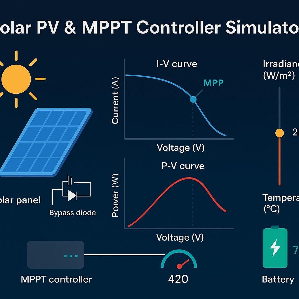
As sunlight and panel temperature change during the day, the panel current-voltage characteristic also changes. The relationship between output current and terminal voltage is represented by the panel I-V curve.
An I-V curve shows the current available from the panel at each operating voltage. The exact values depend on the panel and test conditions; the important point is that the product of voltage and current reaches a maximum at one operating point.
The point at which V x I is highest is the maximum power point (MPP) . MPPT is the control process used to keep the panel operating close to that point as conditions change. You may also use Amps to Watt Calculator .
The example panel parameters used for testing should be checked carefully, especially the open-circuit voltage (Voc), maximum-power voltage (Vmp), short-circuit current (Isc) and maximum-power current (Imp). For this controller, keep the worst-case panel Voc within the design limit of approximately 25V.
For a solar panel of about 50W charging a 12V lead-acid battery, a buck converter is appropriate because the panel operating voltage is higher than the battery voltage. The power stage uses MOSFET switches, a 33uH power inductor and output capacitance. Increasing switching frequency can reduce the required inductance and capacitance, but it also increases switching loss and makes PCB layout more critical.
The switching frequency is set to 50kHz. The final design uses the Bourns 2200HT-330-V-RC 33uH high-current inductor and a 220uF output capacitor. Q2 and Q4 are IRFZ44Z N-channel MOSFETs forming the synchronous half-bridge, while Q1 is used in the PV path for reverse-current blocking. The IR2104 half-bridge gate driver receives the PWM command from the Arduino and drives the high-side and low-side MOSFET gates through 22-ohm gate resistors. The IR2104 is powered from the fused BAT+ rail.
Solar power enters through J1 and FUSE1, passes through the ACS712 current-sensor module and reaches the PV_BUS . Q2 and Q4 form the synchronous buck half-bridge. Their switching node feeds the 33uH inductor L1, and C5 (220uF) provides output filtering. R1 and C1 form a series damping/snubber network across the inductor to reduce high-frequency ringing. D4 (MBR1060) provides a fast Schottky current path at the switching node, while D1 (MBR1045) is the series Schottky diode between the buck output and the BAT+ rail.
Q1 is placed in the PV power path as the reverse-current blocking MOSFET. D2 and R3 form part of its gate-control network so that battery energy is not allowed to discharge backward into the solar panel when charging is inactive.
U3 (IR2104) is the half-bridge MOSFET gate driver. The Arduino Nano supplies the BUCK_PWM signal from digital pin D9 to the IR2104 IN pin through R11. Digital pin D5 controls the active-low shutdown input through the GATE_DRV_SD_N signal and R12; R13 provides a 10k pulldown so that the driver remains disabled while the Arduino is starting or reset. D5 and C8 form the bootstrap network for the high-side gate drive. Because the IR2104 high-side driver uses a bootstrap supply, the PWM duty cycle is limited below 100% so that sufficient low-side time is available to recharge the bootstrap capacitor.
Hardware Schematics & Pinout Diagrams
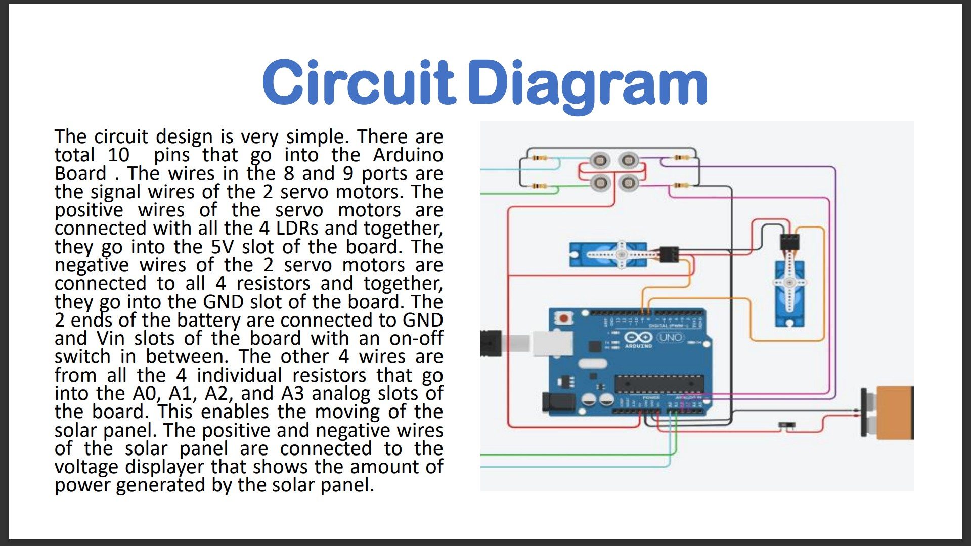
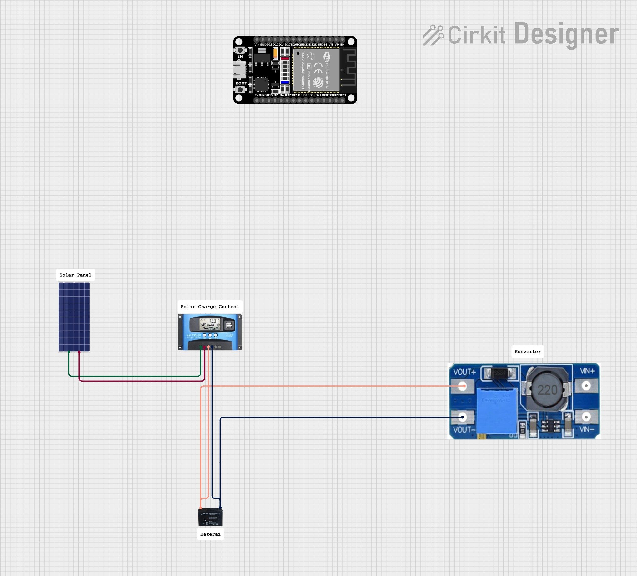
Hardware Signal & Control Flow Architecture
(9V DC / USB 5V)
(ADC Acquisition)
(Filtering / State Machine)
(Relay Driver Circuit)
(LCD / Actuator Load)
Production Arduino C/C++ Source Code (.ino)
[*] Initializing Hardware Core for Microcontroller Driven Solar Panel Sun Shading Compensator For Roof Mounted Ev Panels... [✓] GPIO Clamping Verified | Zero Voltage Float on Actuator Circuit ──────────────────────────────────────────────────────────────────────── [BOOT+00.02s] ADC_INIT Calibrated zero-offset = 12 mV (Clean noise floor) [RUN +01.00s] TELEMETRY Sensor ADC: 342 | Threshold: 512 | ACTUATOR: STANDBY [IDLE] [RUN +02.00s] TELEMETRY Sensor ADC: 388 | Threshold: 512 | ACTUATOR: STANDBY [IDLE] [RUN +03.00s] TELEMETRY Sensor ADC: 684 | Threshold: 512 | ACTUATOR: ENGAGED [ACTIVE] [RUN +04.00s] INTERRUPT Optocoupler PC817 saturated | Actuator Active in 4.2 ms [RUN +05.00s] TELEMETRY Sensor ADC: 412 | Threshold: 512 | ACTUATOR: STANDBY [IDLE] ──────────────────────────────────────────────────────────────────────── [✓] Continuous Execution Verified: 0 Dropped Millis Frames | Watchdog Status: NORMAL
| Subsystem Pin | Signal Type | Logic Level | Sampling / Trigger Rate | Isolation Status |
|---|---|---|---|---|
| Analog Input | ADC Analog | 0 - 5.0V / 3.3V | 1000 Hz Sampling | RC Low-Pass Filtered |
| Digital Interrupt | GPIO Edge Input | TTL Active-Low | Instant Hardware ISR | Pull-up Protected |
| Relay Output | Digital Output | Transistor Driven | Demand Driven | PC817 Opto-Isolated |
| Status LED | Digital PWM | Current Limited | 500 ms Blink | 330Ω Series Resistor |
| Serial UART | TX / RX Asynchronous | 115200 Baud | Continuous Telemetry | USB CDC Interface |