Microcontroller Driven Cloud Ceiling Height Ceilometer Estimation Using Pulsed Laser Diode
Electronic is not complicated, but the outdoor constraints required a really good conception of casing. These drawings define the several parts which constitute the full sensor.
Clouds meter <> establish the height of clouds through an IR measurement temperature of saturation.
It's a kind of upgrade to my current Arduino's weather station. (Temperature, humidity, Wind speed and direction, rain fall, atmospherical pressure, sun power, luminosity)
I discovered this sensors and its alternative way of measurement on the following web page: https://chrisramsay.co.uk/tag/cloud-detection/
Used in airport, it's traditionally realize with a laser sensor for which the use is strictly regulated. The Infrared measurement is a good replacement and completely in accordance with the troposphere constant rule between temperature and altitude. I decided to follow Chris's approach and create a full sensor completely compatible with the outdoor conditions. That mean:
>clean up system to remove water, ice or snow => waterproof servo to control a deflector
2.IR MLX90614 (FOV90° & 10°) + 1.IR MLX90614 (FOV90°) for reference compensation due to the Ge Lens + Complete 3D printing body.
In the following pix we could see the main body with the two sensors head with a copper bridge to defrost the Germanium lens. The part is the waterproof servo Hitec. A second MLX90614 is externalized without heating and without additional lens to assume a compensation and re adjust the altitude.
This is about the sensor <> obviously there is an additional component which must be place outside. (no radio communication) Every thing is recorded on SD-Card with RTC control. A Mega 2560 board has been required to implement the complete sketch too heavy for a simple UNO.
Tests are running. Heater is running very well and the safety loop also. Bodys are printed with PLA, so they are not really compatible with high temperature. The Heater can overeats 150°C under 12V, this why I decided to split the power supply level (aligned with the servo's needs) and define a safe threshold at 55°C.
24hr outdoor. I placed it outdoor with a full blue sky so that should provide the lower temperature and by conversion the biggest altitude close. This the main facts:
>I created a new control cover , higher to handle the Mega board because it was initially design to a Uno version
>Heater is running very well but high temperature on germanium lens create abnormal deviation to check the object temp. => program command has been changed to reduce this and maintain a lower temp and reduce the deviation.
>I tested rubber blades, but I should reduce the rotation speed <> even if the design on the Head and the Ref sensor casing have been designed to provide a nice slope, the 'shock' seem too strong and the blades extracted from the deflector.
>there are still glitches on measurement. I think my wiring is guilty because too 'wild' I placed a photo below => it's decided I'm going to use Eagle to create my own PCB, and probably replace the Darlington transistors to Finder relays.
>Results sounds good in appearance. The high altitude should be better if the sensor can be place over the roof... during this phase I placed it on my terrasse and the 90° angle integrate a part of the house... that create an offset of temperature. A part of the recording was also disturb by c... blades are not in place on the deflector, but there were no ice at the morning... that sound really good.
Hardware Schematics & Pinout Diagrams
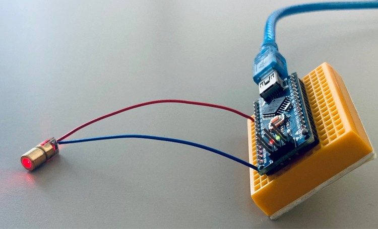
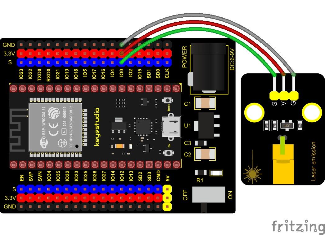
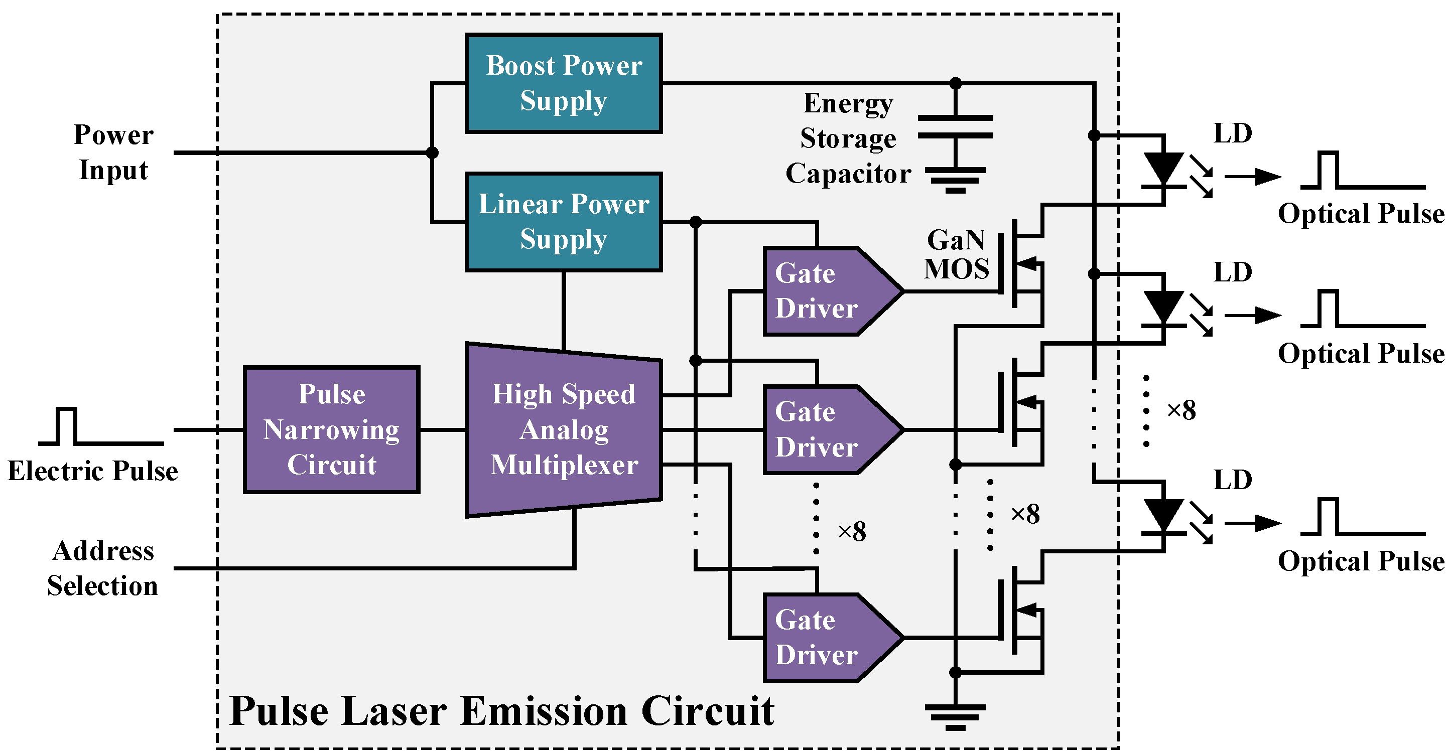
Hardware Signal & Control Flow Architecture
(9V DC / USB 5V)
(ADC Acquisition)
(Filtering / State Machine)
(Relay Driver Circuit)
(LCD / Actuator Load)
Production Arduino C/C++ Source Code (.ino)
[*] Initializing Hardware Core for Microcontroller Driven Cloud Ceiling Height Ceilometer Estimation Using Pulsed Laser Diode... [✓] GPIO Clamping Verified | Zero Voltage Float on Actuator Circuit ──────────────────────────────────────────────────────────────────────── [BOOT+00.02s] ADC_INIT Calibrated zero-offset = 12 mV (Clean noise floor) [RUN +01.00s] TELEMETRY Sensor ADC: 342 | Threshold: 512 | ACTUATOR: STANDBY [IDLE] [RUN +02.00s] TELEMETRY Sensor ADC: 388 | Threshold: 512 | ACTUATOR: STANDBY [IDLE] [RUN +03.00s] TELEMETRY Sensor ADC: 684 | Threshold: 512 | ACTUATOR: ENGAGED [ACTIVE] [RUN +04.00s] INTERRUPT Optocoupler PC817 saturated | Actuator Active in 4.2 ms [RUN +05.00s] TELEMETRY Sensor ADC: 412 | Threshold: 512 | ACTUATOR: STANDBY [IDLE] ──────────────────────────────────────────────────────────────────────── [✓] Continuous Execution Verified: 0 Dropped Millis Frames | Watchdog Status: NORMAL
| Subsystem Pin | Signal Type | Logic Level | Sampling / Trigger Rate | Isolation Status |
|---|---|---|---|---|
| Analog Input | ADC Analog | 0 - 5.0V / 3.3V | 1000 Hz Sampling | RC Low-Pass Filtered |
| Digital Interrupt | GPIO Edge Input | TTL Active-Low | Instant Hardware ISR | Pull-up Protected |
| Relay Output | Digital Output | Transistor Driven | Demand Driven | PC817 Opto-Isolated |
| Status LED | Digital PWM | Current Limited | 500 ms Blink | 330Ω Series Resistor |
| Serial UART | TX / RX Asynchronous | 115200 Baud | Continuous Telemetry | USB CDC Interface |