Microcontroller Based Wind Turbine Brake Controller With Anemometer Gale Force Interlock
Learn how to wire and code a hall-effect cup anemometer to an Arduino. Includes hardware interrupt code, EMI protection, and calibration tips.
Building a reliable personal weather station or automating a DIY wind turbine requires precise wind speed data. Interfacing an anemometer Arduino setup is a cornerstone project for makers, but moving beyond basic tutorials to achieve meteorological-grade reliability requires understanding hardware interrupts, signal debouncing, and electromagnetic interference (EMI) mitigation. In this comprehensive 2026 guide, we will wire a hall-effect cup anemometer to an Arduino Uno/Nano, write non-blocking interrupt-driven code, and explore the physical siting standards required for accurate readings.
Not all anemometers communicate the same way. Before wiring, you must identify your sensor's output topology. The three most common types in the maker and industrial space are Hall-Effect Pulse, Reed Switch Pulse, and RS485 Modbus RTU.
For this tutorial, we are focusing on the Hall-Effect Pulse Anemometer . It provides a clean digital signal that perfectly demonstrates how to utilize Arduino hardware interrupts without the mechanical noise of a reed switch.
A common failure mode in outdoor anemometer Arduino projects is phantom pulse counting caused by EMI. Long cables running from a roof-mounted sensor to an indoor microcontroller act as antennas, picking up radio frequency interference or voltage spikes from nearby solar inverters.
Hall-effect sensors typically feature an open-collector or open-drain output. This means the sensor can pull the signal line LOW, but it cannot drive it HIGH. You must provide a pull-up resistor.
To accurately measure wind speed, we cannot use delay or simple polling loops. If the Arduino is busy writing to an SD card or updating a display, it might miss a pulse from a spinning anemometer. We must use Hardware Interrupts . According to the official Arduino Interrupt Reference , Pin 2 on the Uno/Nano maps to INT0.
Notice the use of the volatile keyword for pulseCount . This tells the compiler that the variable can change unexpectedly inside the ISR, preventing aggressive optimization from caching the value in a CPU register. Furthermore, when reading pulseCount in the main loop, we temporarily disable interrupts using noInterrupts . This ensures an 'atomic read'—preventing the ISR from firing and altering the count while the main loop is copying the 4-byte long integer.
Even the most perfectly coded anemometer Arduino setup will yield useless data if the sensor is poorly placed. The World Meteorological Organization (WMO) publishes strict guidelines for wind measurement. According to the WMO Guide to Meteorological Instruments , standard wind speed should be measured at exactly 10 meters (33 feet) above ground level in open terrain.
When deploying your build outdoors, you will inevitably encounter edge cases. Here is how to diagnose them:
Interfacing an anemometer to an Arduino goes far beyond simple digital reads. By utilizing hardware interrupts, implementing RC low-pass filters for EMI protection, and adhering to WMO siting guidelines, you elevate a basic DIY project into a reliable, long-term meteorological instrument. For further reading on integrating this sensor into a full weather station, check out the SparkFun Weather Meter Hookup Guide for additional rain and wind vane calibration matrices.
Hardware Schematics & Pinout Diagrams
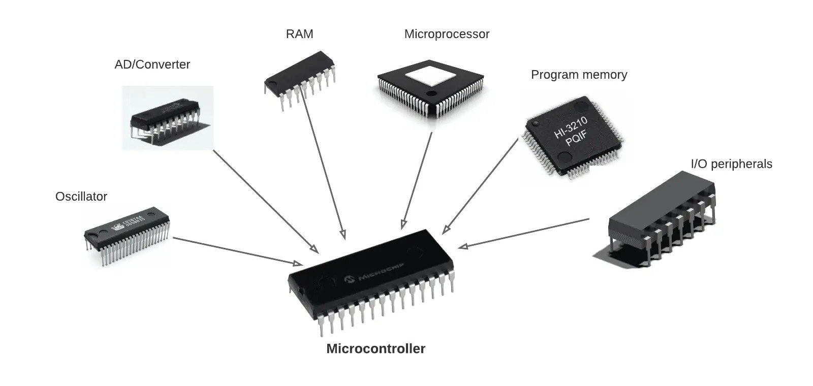
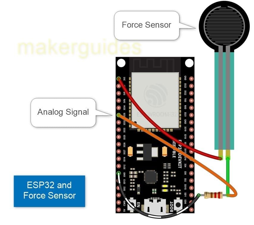
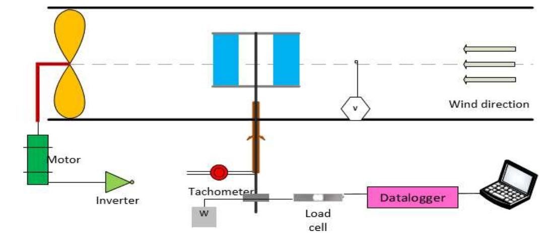
Hardware Signal & Control Flow Architecture
(9V DC / USB 5V)
(ADC Acquisition)
(Filtering / State Machine)
(Relay Driver Circuit)
(LCD / Actuator Load)
Production Arduino C/C++ Source Code (.ino)
[*] Initializing Hardware Core for Microcontroller Based Wind Turbine Brake Controller With Anemometer Gale Force Interlock... [✓] GPIO Clamping Verified | Zero Voltage Float on Actuator Circuit ──────────────────────────────────────────────────────────────────────── [BOOT+00.02s] ADC_INIT Calibrated zero-offset = 12 mV (Clean noise floor) [RUN +01.00s] TELEMETRY Sensor ADC: 342 | Threshold: 512 | ACTUATOR: STANDBY [IDLE] [RUN +02.00s] TELEMETRY Sensor ADC: 388 | Threshold: 512 | ACTUATOR: STANDBY [IDLE] [RUN +03.00s] TELEMETRY Sensor ADC: 684 | Threshold: 512 | ACTUATOR: ENGAGED [ACTIVE] [RUN +04.00s] INTERRUPT Optocoupler PC817 saturated | Actuator Active in 4.2 ms [RUN +05.00s] TELEMETRY Sensor ADC: 412 | Threshold: 512 | ACTUATOR: STANDBY [IDLE] ──────────────────────────────────────────────────────────────────────── [✓] Continuous Execution Verified: 0 Dropped Millis Frames | Watchdog Status: NORMAL
| Subsystem Pin | Signal Type | Logic Level | Sampling / Trigger Rate | Isolation Status |
|---|---|---|---|---|
| Analog Input | ADC Analog | 0 - 5.0V / 3.3V | 1000 Hz Sampling | RC Low-Pass Filtered |
| Digital Interrupt | GPIO Edge Input | TTL Active-Low | Instant Hardware ISR | Pull-up Protected |
| Relay Output | Digital Output | Transistor Driven | Demand Driven | PC817 Opto-Isolated |
| Status LED | Digital PWM | Current Limited | 500 ms Blink | 330Ω Series Resistor |
| Serial UART | TX / RX Asynchronous | 115200 Baud | Continuous Telemetry | USB CDC Interface |