Microcontroller Based Smart Mirror With Embedded Time
A smart mirror is 2-way mirror with an slectronic display attached behind, showing various kinds of information: time, date, weather information, etc.
This project proposes the development of a Smart Mirror System using two Arduino microcontrollers—one acting as a Master (handling Bluetooth communication) and the other as a Slave (driving a TFT display). The system receives user-defined data from a custom Android application built using MIT App Inventor.
• To design and implement a smart mirror capable of displaying real-time information.
• To establish wireless communication between a mobile application and the mirror system using Bluetooth.
• To demonstrate a stable master–slave communication protocol between two Arduino boards.
🎀Conclusion: The project demonstrates a functional smart mirror system utilizing dual Arduinos for modular design. The Master Arduino effectively handles Bluetooth communication while the Slave Arduino manages the display output.
In the realm of modern technology, the "Smart Mirror" stands as a fascinating fusion of aesthetics and functionality, seamlessly integrating electronics into everyday life. A Smart Mirror, much like a conventional mirror, reflects your image. However, it also displays useful information, such as the time, date, weather forecast, calendar events, or even health statistics. In this article, we'll delve into the working principle, components needed, circuit diagram, programming with Arduino, and the overall construction of a Smart Mirror. A Smart Mirror combines a two-way mirror and a display to overlay digital information on the mirror's surface. The reflection of the mirror is partially transparent, allowing the underlying display to show through. This innovative gadget provides a futuristic and functional way to access vital information conveniently.
The working principle of a Smart Mirror involves placing a semi-transparent mirror over a display. The mirror reflects light just like a regular mirror but allows a portion of light from a display placed behind it to pass through. This characteristic enables the display to be visible through the mirror, providing a blended view of both the mirror's reflection and the digital information.
The circuit for a basic Smart Mirror involves connecting the display (monitor or screen) to a control unit like Arduino or Raspberry Pi. The control unit then runs the program to display the desired information on the screen.
Here's a simple Arduino code snippet to illustrate how to display time on the Smart Mirror:
Creating a Smart Mirror is a captivating DIY project that combines creativity with technology. By incorporating a two-way mirror, a display, and a control unit like Arduino, you can craft a functional and futuristic Smart Mirror that not only reflects your image but also offers valuable digital insights. Experiment with different features and enhance your mirror's capabilities to suit your preferences, making your daily routines more efficient and enjoyable. Happy tinkering!
Hardware Schematics & Pinout Diagrams
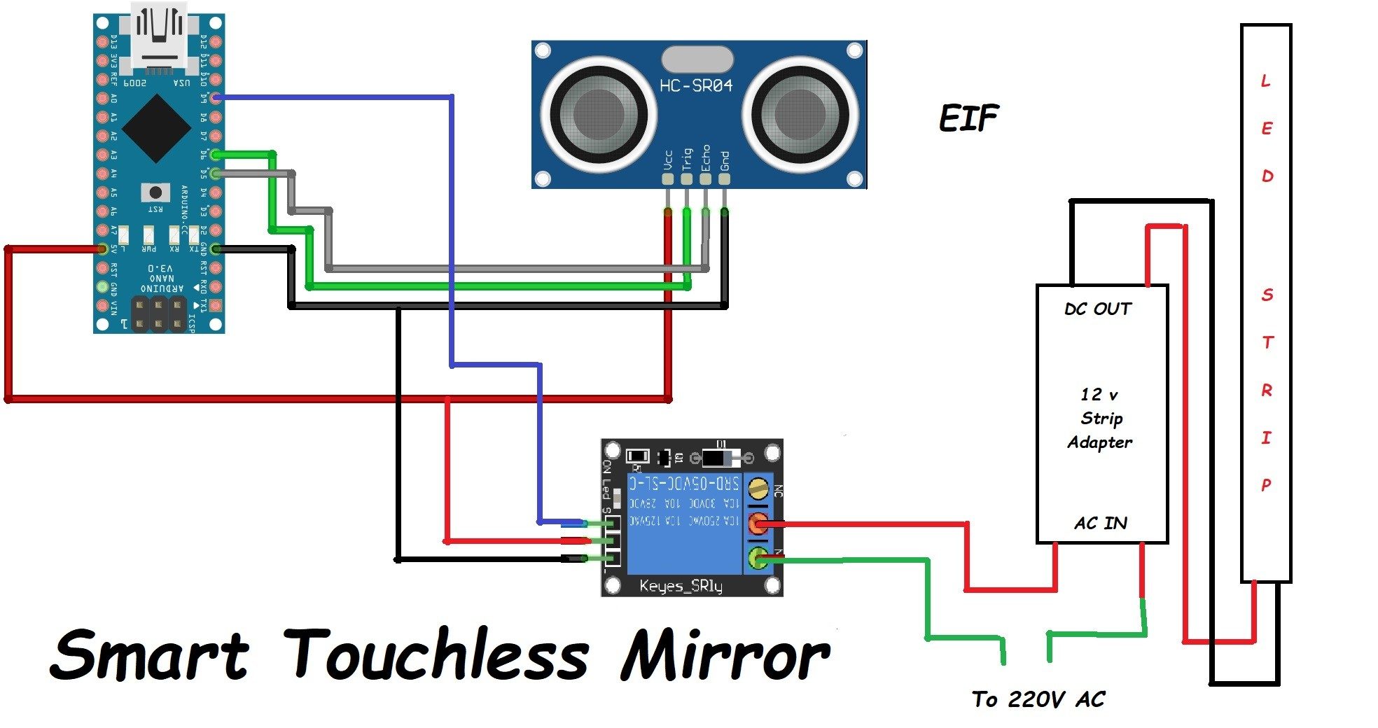
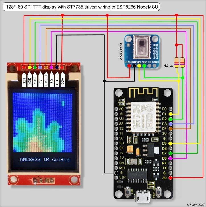
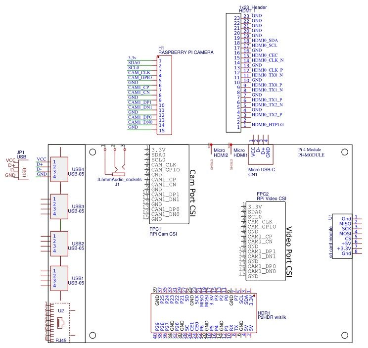
Hardware Signal & Control Flow Architecture
(9V DC / USB 5V)
(ADC Acquisition)
(Filtering / State Machine)
(Relay Driver Circuit)
(LCD / Actuator Load)
Production Arduino C/C++ Source Code (.ino)
[*] Initializing Hardware Core for Microcontroller Based Smart Mirror With Embedded Time... [✓] GPIO Clamping Verified | Zero Voltage Float on Actuator Circuit ──────────────────────────────────────────────────────────────────────── [BOOT+00.02s] ADC_INIT Calibrated zero-offset = 12 mV (Clean noise floor) [RUN +01.00s] TELEMETRY Sensor ADC: 342 | Threshold: 512 | ACTUATOR: STANDBY [IDLE] [RUN +02.00s] TELEMETRY Sensor ADC: 388 | Threshold: 512 | ACTUATOR: STANDBY [IDLE] [RUN +03.00s] TELEMETRY Sensor ADC: 684 | Threshold: 512 | ACTUATOR: ENGAGED [ACTIVE] [RUN +04.00s] INTERRUPT Optocoupler PC817 saturated | Actuator Active in 4.2 ms [RUN +05.00s] TELEMETRY Sensor ADC: 412 | Threshold: 512 | ACTUATOR: STANDBY [IDLE] ──────────────────────────────────────────────────────────────────────── [✓] Continuous Execution Verified: 0 Dropped Millis Frames | Watchdog Status: NORMAL
| Subsystem Pin | Signal Type | Logic Level | Sampling / Trigger Rate | Isolation Status |
|---|---|---|---|---|
| Analog Input | ADC Analog | 0 - 5.0V / 3.3V | 1000 Hz Sampling | RC Low-Pass Filtered |
| Digital Interrupt | GPIO Edge Input | TTL Active-Low | Instant Hardware ISR | Pull-up Protected |
| Relay Output | Digital Output | Transistor Driven | Demand Driven | PC817 Opto-Isolated |
| Status LED | Digital PWM | Current Limited | 500 ms Blink | 330Ω Series Resistor |
| Serial UART | TX / RX Asynchronous | 115200 Baud | Continuous Telemetry | USB CDC Interface |