Microcontroller Based Smart Door Lock With Capacitive Fingerprint Sensor And Keypad Fallback
In today’s world, security plays a crucial role in our everyday lives. One innovative solution is a fingerprint door lock system that offers enhanced security and convenience. In this article, we will explore how to build a fingerprint door lock system using Arduino, a versatile microcontroller platform. By following the steps outlined below, you can create your own biometric security system.
Fingerprint sensors are electronic devices that capture and analyze the unique patterns of ridges and valleys on an individual’s fingertip. They are commonly used for biometric authentication, as fingerprints are unique to each person and can be used as a reliable means of identification.
The main component of the module is a relay, which is an electrically operated switch. The relay consists of an electromagnet and a set of contacts. When the electromagnet is energized, it mechanically activates the contacts, either connecting or disconnecting the circuit.
A 16×2 LCD display with I2C interface refers to a liquid crystal display (LCD) module that has 16 columns and 2 rows of characters and uses the I2C (Inter-Integrated Circuit) communication protocol for interfacing with other devices.
The module is equipped with an integrated I2C interface, which is a widely used serial communication protocol. The I2C interface allows for easy communication between the LCD module and other devices, such as microcontrollers or Arduino boards, using only two wires: SDA (data line) and SCL (clock line).
A solenoid lock is an electromechanical device used for securing doors or other access points. It consists of a solenoid, which is an electromagnetic coil, and a locking mechanism. When activated, the solenoid generates a magnetic field that moves the locking mechanism, either engaging or disengaging it to lock or unlock the door.
And We Connected To the 2 LEDs red And green When We put the finger on the Fingerprint Sensor if the finger is valid then Green LED will Be On If is not Valid Then Red Led Will Be ON.
Building a fingerprint door lock system with Arduino provides an exciting opportunity to enhance security and convenience in your home or office. By integrating an Arduino board, fingerprint sensor module, and lock mechanism, you can create a reliable biometric security system. Following the outlined steps, you’ll be on your way to implementing your own personalized fingerprint door lock system.
Build an Arduino smart door lock using an R307 fingerprint sensor and a 12V linear actuator. This tutorial covers the...
Learn 8051 programming with Keil µVision using the AT89S52 development board. Follow step-by-step instructions to cre...
Learn how to charge a 3.7V Li-ion or 18650 battery safely using a TP4056 module and a 5V USB supply. This guide cover...
Learn how to connect the ADXL345 3-axis accelerometer to Arduino, read X, Y, and Z acceleration, and calculate pitch ...
Smart locks have become one of the most popular home automation projects because they combine electronics, programming, and practical problem-solving into a single build. Whether you're learning Arduino for the first time or looking to expand your DIY portfolio, building your own smart lock helps you understand how microcontrollers interact with sensors, actuators, and authentication systems. In this guide, you'll learn how to build a smart door lock using Arduino , including the required components, wiring, and implementation process. Along the way, you'll also gain hands-on experience with servo motors, RFID technology, and embedded programming.
Having all the components ready before assembly makes the project easier to build and troubleshoot.
This simple workflow demonstrates how embedded systems make decisions based on sensor input before controlling physical hardware.
Building a smart door lock using arduino introduces several important electronics and programming concepts in a single project.
Tip: Although small servo motors can sometimes run directly from the Arduino, using an external power supply results in more stable operation and prevents unexpected resets.
Begin by connecting the RFID reader to the Arduino according to the wiring table above.
Next, connect the servo motor to its control pin while ensuring both the Arduino and the external power supply share a common ground.
Before uploading the program, install the necessary Arduino libraries through the Arduino IDE.
Before the lock can be used, you'll need to record the UID of your RFID card or key fob.
Upload a simple RFID reading example from the MFRC522 library and open the Serial Monitor.
Copy this UID into your main access-control program so that only authorized cards can unlock the door.
This step forms the core of the smart door lock using Arduino, allowing authentication to be customized for different users.
After uploading the program and registering your RFID card, it's time to test the system.
Next, test the system using an unauthorized RFID card. The servo should remain in the locked position, ensuring only registered users can access the lock.
Testing both authorized and unauthorized scenarios helps confirm that the authentication logic is functioning correctly.
Once the prototype works reliably on a breadboard, assemble the components into a more permanent setup.
Secure the Arduino, RFID reader, and servo motor inside a suitable enclosure. Position the RFID reader where users can easily tap their access card, while ensuring the servo is firmly attached to the locking mechanism.
For long-term use, replacing the breadboard with a custom PCB or perfboard improves reliability by eliminating loose jumper wire connections.
A working prototype often fails because of poor cable management rather than faulty code.
Good wiring practices make the project easier to maintain and significantly improve long-term reliability.
Before considering the project complete, test it repeatedly under normal operating conditions.
Running multiple test cycles helps identify intermittent issues that may not appear during initial testing.
If the project doesn't work as expected, the following table can help identify the problem.
Most issues can be resolved by checking wiring carefully before modifying the program.
Once your smart door lock using Arduino is working, there are several ways to make it more capable.
Each upgrade introduces new programming concepts while making the project more suitable for real-world applications.
Projects like this provide an excellent foundation for learning embedded systems because they combine sensors, actuators, and programming into a practical application.
If you enjoyed working with RFID technology, our guide on Building a Smart Attendance System demonstrates how the same RFID module can be used to record attendance automatically, introducing concepts such as database integration and access logging.
Looking for another beginner-friendly automation project? Explore Build a Smart Plant Watering System Under ₹1500 to learn how Arduino can monitor environmental conditions and automate everyday tasks using sensors and relays.
Building a smart door lock using Arduino is an excellent way to combine electronics, programming, and automation into a practical project. Beyond learning how RFID authentication works, you'll gain experience interfacing multiple hardware components, controlling actuators, and implementing access control logic using a microcontroller.
As your skills grow, this project can become the foundation for more advanced smart home systems by incorporating biometric authentication, IoT connectivity, or mobile app integration. Whether you're building it as a learning exercise, an engineering project, or the start of a home automation setup, a smart door lock using Arduino demonstrates how simple electronic components can be combined to create reliable, real-world solutions.
In this project, we will build a Biometric Security System using Arduino and a Fingerprint Sensor . Biometric security systems are becoming increasingly popular due to their enhanced security features and ease of use. Unlike traditional security systems that rely on passwords or physical keys, biometric systems use unique physical or behavioral characteristics, such as fingerprints, to verify an individual’s identity.
By integrating the Arduino microcontroller with a fingerprint sensor, we can create a reliable and efficient security system that can be used for various applications, from door locks to attendance systems. The Arduino processes the data from the fingerprint sensor and determines whether access should be granted or denied based on the stored fingerprint data . This project offers a hands-on approach to understanding the intricacies of biometric security and the potential of Arduino in real-world applications.
Earlier we build Password based Security System as well as RFID Security System using an Arduino. You may follow them for more security system projects.
The following are the components required for making this project.
All these components can be connected in a breadboard to build the complete system.
Here’s the block diagram of the Biometric Security System using Arduino and Fingerprint Sensor:
Hardware Schematics & Pinout Diagrams
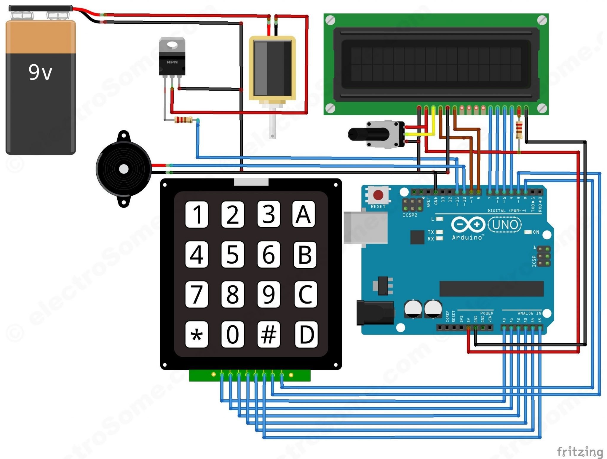
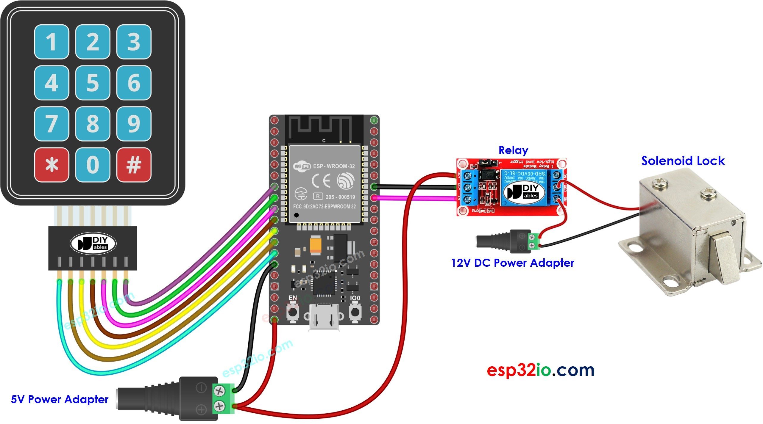
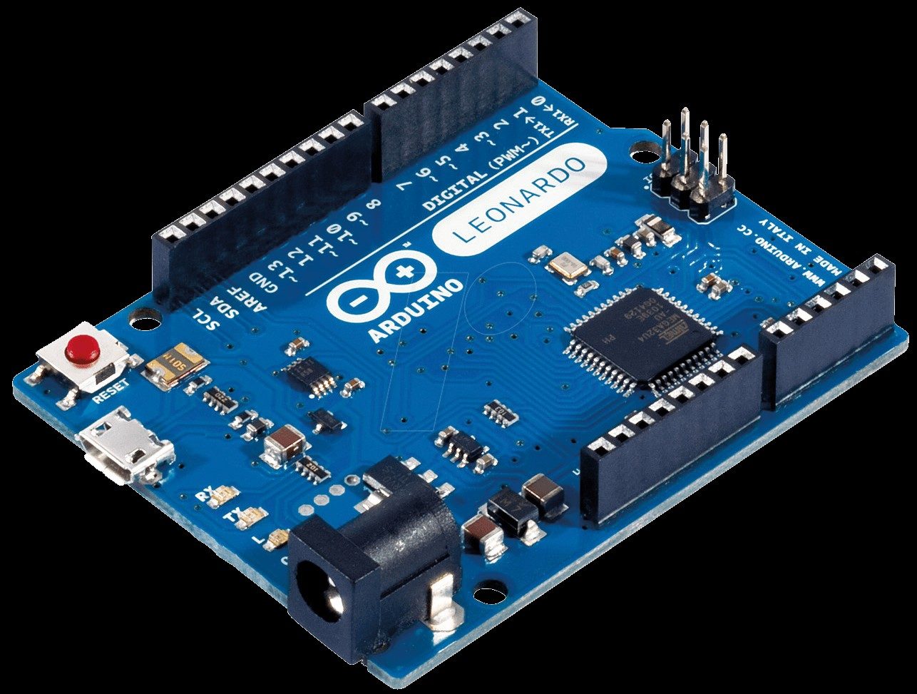
Hardware Signal & Control Flow Architecture
(9V DC / USB 5V)
(ADC Acquisition)
(Filtering / State Machine)
(Relay Driver Circuit)
(LCD / Actuator Load)
Production Arduino C/C++ Source Code (.ino)
[*] Initializing Hardware Core for Microcontroller Based Smart Door Lock With Capacitive Fingerprint Sensor And Keypad Fallback... [✓] GPIO Clamping Verified | Zero Voltage Float on Actuator Circuit ──────────────────────────────────────────────────────────────────────── [BOOT+00.02s] ADC_INIT Calibrated zero-offset = 12 mV (Clean noise floor) [RUN +01.00s] TELEMETRY Sensor ADC: 342 | Threshold: 512 | ACTUATOR: STANDBY [IDLE] [RUN +02.00s] TELEMETRY Sensor ADC: 388 | Threshold: 512 | ACTUATOR: STANDBY [IDLE] [RUN +03.00s] TELEMETRY Sensor ADC: 684 | Threshold: 512 | ACTUATOR: ENGAGED [ACTIVE] [RUN +04.00s] INTERRUPT Optocoupler PC817 saturated | Actuator Active in 4.2 ms [RUN +05.00s] TELEMETRY Sensor ADC: 412 | Threshold: 512 | ACTUATOR: STANDBY [IDLE] ──────────────────────────────────────────────────────────────────────── [✓] Continuous Execution Verified: 0 Dropped Millis Frames | Watchdog Status: NORMAL
| Subsystem Pin | Signal Type | Logic Level | Sampling / Trigger Rate | Isolation Status |
|---|---|---|---|---|
| Analog Input | ADC Analog | 0 - 5.0V / 3.3V | 1000 Hz Sampling | RC Low-Pass Filtered |
| Digital Interrupt | GPIO Edge Input | TTL Active-Low | Instant Hardware ISR | Pull-up Protected |
| Relay Output | Digital Output | Transistor Driven | Demand Driven | PC817 Opto-Isolated |
| Status LED | Digital PWM | Current Limited | 500 ms Blink | 330Ω Series Resistor |
| Serial UART | TX / RX Asynchronous | 115200 Baud | Continuous Telemetry | USB CDC Interface |