Microcontroller Based Secure Communication Node Using Elliptic Curve Diffie Hellman Ecdh
GAP is the layer of the BLE stack which determines the network topology of the BLE system. Based on this layer, there are two roles in the BLE communication: BLE GAP Central and BLE GAP Peripheral .
The GAP Central is typically the device which initiates the connection with the GAP Peripheral. Once the two devices are connected, they will perform a “pairing” process where they will exchange the information necessary to establish an encrypted connection.
GATT is the layer of the BLE stack used by the application for data communication between two connected devices. Data is passed and stored in the form of characteristics which are stored in memory of BLE device. When two devices are connected, they obtain one of two roles: GATT Server and GATT Client .
The GATT Server is the device containing the characteristic database that is being read or written by a GATT Client. Consider characteristics as groups of information called attributes.
Max number of bytes that is possible to transfer over GATT layer at once is 20–23. Real number depends on how long GATT specific messages are.
Pairing is the process by which two BLE devices exchange device information so that secure link can be established. The process varies somewhat between the BLE 4.2 devices and the older 4.1 and 4.0 devices.
In BLE 4.2, devices use ECDH key exchange in their pairing process. The only problem with ECDH key exchange is that it does not give the user a way to verify the authenticity of the connection . Therefore, it is still vulnerable to MITM attacks.
Refer to this article about security mechanism for clustered wireless sensor networks based on elliptic curve cryptography.
...uses arithmetic in a multiplicative group with generator G . Exponents arduino and android are chosen randomly by Arduino and Android respectively and are used to form the session key K .
... SIG represents the signature by the principal X on the string in the brackets while { M } denotes symmetric encryption of message M using key K. The particular signature algorithm chosen does not matter for the protocol...
[Boyd, C.; Mathuria, A.: "Protocols for Authentication and Key Establishment", Springer, 1998.]
Symmetric , i.e. session key , is created by applying SHA-256 cryptographic hash function on the shared secret generated during Elliptic-Curve Diffie-Hellman key exchange protocol.
State Machines in general represent a set of complex rules and conditions. For the purpose of this project, State Machine is created in order to simplify execution of Elliptic-curve Diffie-Hellman key exchange protocol and also to simulate its states and transitions. The same State Machine is implemented on both, Arduino Uno board and Android device.
All messages exchanged during both, key exchange protocol and encrypted communication, have the following template: $
For the purpose of this project, Arduino Uno is used along with Bluetooth module HM-10.
Secure communication between Arduino Uno microcontroller and Android application over BLE (Bluetooth Low Energy).
This is a library for implementing Elliptic Curve Cryptography (ECC) and Elliptic Curve Digital Signature Algorithm (ECDSA) on Arduino-based microcontrollers.
To set mapping table, edit the tinyECC_mapping_table.h file. Uncomment the appropriate line to define your mapping table in the tinyECC_mapping_table.h file as shown below:
Hardware Schematics & Pinout Diagrams
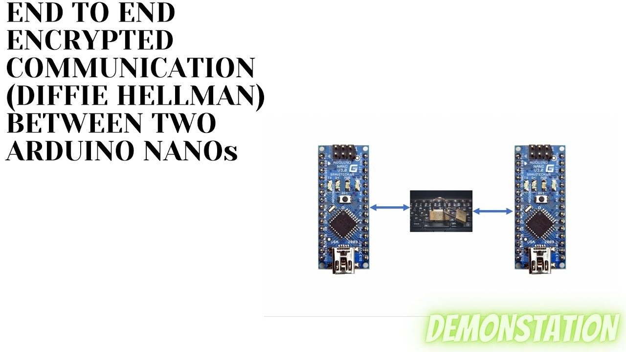
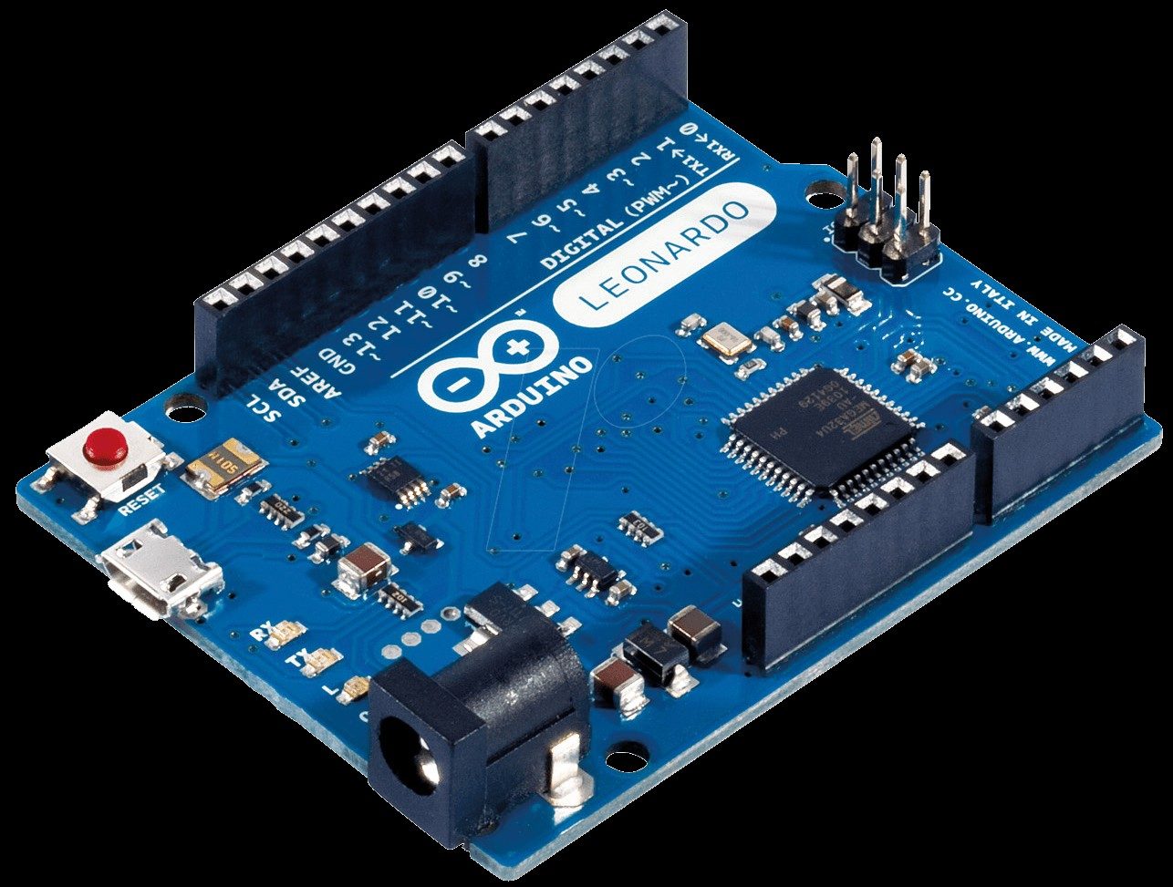
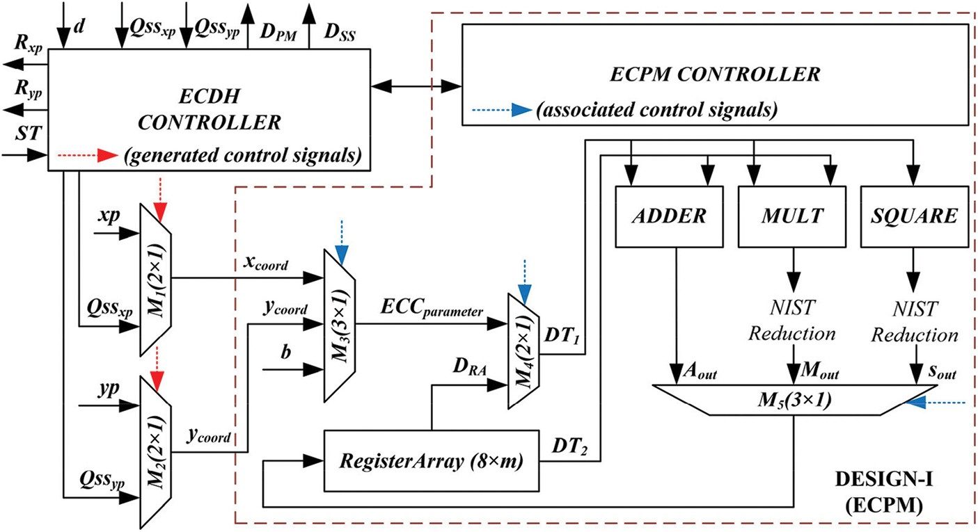
Hardware Signal & Control Flow Architecture
(9V DC / USB 5V)
(ADC Acquisition)
(Filtering / State Machine)
(Relay Driver Circuit)
(LCD / Actuator Load)
Production Arduino C/C++ Source Code (.ino)
[*] Initializing Hardware Core for Microcontroller Based Secure Communication Node Using Elliptic Curve Diffie Hellman Ecdh... [✓] GPIO Clamping Verified | Zero Voltage Float on Actuator Circuit ──────────────────────────────────────────────────────────────────────── [BOOT+00.02s] ADC_INIT Calibrated zero-offset = 12 mV (Clean noise floor) [RUN +01.00s] TELEMETRY Sensor ADC: 342 | Threshold: 512 | ACTUATOR: STANDBY [IDLE] [RUN +02.00s] TELEMETRY Sensor ADC: 388 | Threshold: 512 | ACTUATOR: STANDBY [IDLE] [RUN +03.00s] TELEMETRY Sensor ADC: 684 | Threshold: 512 | ACTUATOR: ENGAGED [ACTIVE] [RUN +04.00s] INTERRUPT Optocoupler PC817 saturated | Actuator Active in 4.2 ms [RUN +05.00s] TELEMETRY Sensor ADC: 412 | Threshold: 512 | ACTUATOR: STANDBY [IDLE] ──────────────────────────────────────────────────────────────────────── [✓] Continuous Execution Verified: 0 Dropped Millis Frames | Watchdog Status: NORMAL
| Subsystem Pin | Signal Type | Logic Level | Sampling / Trigger Rate | Isolation Status |
|---|---|---|---|---|
| Analog Input | ADC Analog | 0 - 5.0V / 3.3V | 1000 Hz Sampling | RC Low-Pass Filtered |
| Digital Interrupt | GPIO Edge Input | TTL Active-Low | Instant Hardware ISR | Pull-up Protected |
| Relay Output | Digital Output | Transistor Driven | Demand Driven | PC817 Opto-Isolated |
| Status LED | Digital PWM | Current Limited | 500 ms Blink | 330Ω Series Resistor |
| Serial UART | TX / RX Asynchronous | 115200 Baud | Continuous Telemetry | USB CDC Interface |