Microcontroller Based Resistance Measurement Against Side Channel Power Attacks
Recently, I observed people implementing cryptography for Arduino by themselves like state in this topic in stackoverflow:
https://stackoverflow.com/questions/39189065/rsa-encryption-decryption-functions-for-arduino
Several of them can be found over the internet, some by the way are in well-knowm libraries.
I decide to do this small PoC ( Proof of concept )to show why is important not invented your own cryptography algorithm, but also use a robust implementation of such a algorithms.
This PoC performs an side channel attack ( power analysis attack ) against a bad implementation of an auxiliary routine used in the RSA implementation ( fast exponentiation).
A side-channel attack is a method of compromising a cryptographic system by exploiting indirect information leakage rather than directly attacking the cryptographic algorithm or protocol itself.
This type of leakage can originate from various sources such as timing information, power consumption, electromagnetic emissions, or even sound.
Such attacks can be highly effective in compromising cryptographic systems like RSA without requiring the attacker to solve the underlying mathematical problems that ensure the security of the cryptographic scheme (Kocher, Jaffe, & Jun, 1999).
This paper will perform a power analysis attack on a well-known vulnerability in an implementation of the RSA algorithm in a firmware for Arduino ( Atmega328P).
Note I did it on the rush, please forgive me for the spells / grammar errors that eventually you will find.
Power analysis attacks involve measuring the power consumption of a device during cryptographic operations.
Differential Power Analysis (DPA) involves statistical analysis of power consumption patterns across multiple cryptographic operations to extract secrets, making it more sophisticated than Simple Power Analysis (SPA), which directly correlates power fluctuations with specific cryptographic operations to deduce secrets.
Differential Power Analysis (DPA) and Simple Power Analysis (SPA) can be used to extract private keys by analyzing patterns in power consumption during RSA computations.
These attacks can reveal the private key by identifying distinct power usage patterns associated with different key bits (Kocher, Jaffe, & Jun, 1999).
RSA (Rivest-Shamir-Adleman) is a widely used public-key encryption algorithm named after its inventors: Ron Rivest, Adi Shamir, and Leonard Adleman, who introduced it in 1977 (Paar & Pelzl, 2010).
It remains one of the most secure methods for transmitting data securely over the internet.
One of the foundations of RSA's security lies in the difficulty of factoring large composite numbers into their prime factors (Menezes, van Oorschot, & Vanstone, 1996).
This problem, known as the factoring problem, involves finding the prime numbers that multiply together to form a given large number.
RSA encryption relies on the assumption that this factoring problem is computationally difficult enough to make it impractical to break the encryption by factoring the modulus into its prime factors (Menezes, van Oorschot, & Vanstone, 1996).
The Figure 1 illustrates the RSA encryption and decryption process using a simple example.
Please note that in this case, 3 and 33 are public. The number 7 in the example is the private key.
The Phi (N) function, Euler's totient function, computes all coprime numbers in the interval from 1 to 33 .
The value 33 is obtained from the multiplication of P and Q ; in this case, 11 multiplied by 3 .
The result of the Phi function is obtained by multiplying (P - 1) by (Q - 1) ; in this case, 10 multiplied by 2 .
The operation e-1 mod 20 denotes the modular inverse operation (Menezes, van Oorschot, & Vanstone, 1996).
Note: If you wish to delve deeper into RSA, which is not necessary to understand this paper. There is a quick introduction to these basic number theory operations within this repository the file number_theory.md . The explanation can enhance your understanding of RSA operations.
The experiment used an osciloscope DS1102 (presented in the Figure 2 ) manufactured by Rigol.
The osciloscope's manual can be found in the references (RIGOL Technologies, Inc., 2017).
Ohm's Law is a fundamental principle in the field of electrical engineering and physics.
It states that the current flowing through a conductor between two points is directly proportional to the voltage across the two points and inversely proportional to the resistance between them (Boylestad, 2015).
The Ohm law implies that if you increase the voltage across a conductor, the current will also increase, provided the resistance remains constant(Johnson & Hilburn, 2013). Figure 5 present an example of Ohm's law application which the goal is to find the current in the circuit.
Kirchhoff's Voltage Law (KVL) is a fundamental principle in electrical engineering and physics (Boylestad, 2015).
It states that the sum of all electrical potential differences (voltages) around any closed network or loop is zero (Boylestad, 2015).
There is an example of the Kirchhoff's law's application in the Figure 7 in order to find the current over the resistors R1 and R2 .
The voltage divider is a consequence of Kirchhoff's Voltage Law (KVL) and states a way to calculates the Vout that is the voltage between the resistor R1 and R2 .
A shunt resistor is a low-value resistor placed in series with the circuit's power supply to measure the current flowing through the circuit.
Using a Shunt to meansure current is one of the techniques utlized in modern multimeters. (Boylestad, 2015).
Measuring the voltage drop across the shunt resistor and knowing its resistance gives enough information to calculate the current using Ohm's Law.
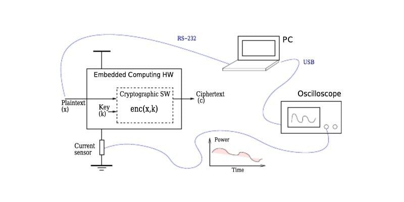
To measure the current consumption of an Arduino device it is need to place a shunt resistor in series with the VCC ( positive ).
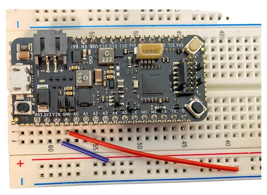
Note 1: Please note that in the PoC, instead use the arduino Uno board the target ( microcontroller atmega328p) is transfered to a separated breadboard as presented in the Figure 11 . It allows to easier manipulate the pinout of the microcontroller not requiring soldering.
Note 2: If you don't know how to do that, my previous article showing how glitching works teaches how to do that and can be found at )
To demonstrate the measurement of current consumption using a shunt resistor , a LED (Sedra & Smith, 2014) will be connected to the microcontroller's GPIO ( Figure12 ) and the osciloscope will be used to observe how it affects the power consumption over the shunt resistor in the situations where the LED is on or off.
Observe to extract the Key or observing the charger effect over the power consumption is not needed to use the Ohms law to obtain the current, only the voltage drop is already enough (Johnson & Hilburn, 2013).
To better observe it, please check the Video 1 which shows how the voltage drop when led is on.
The following code was utilized to blink the led. It also can be found in this repository.
It is important to state that this voltage drop also occurs when an complex calculation happens (Kocher, Jaffe, & Jun, 1999).
If the voltage drop reflects of calculation, thus it can be used to determine the data which is being processed.
The conventional way to perform the power operation is multipling the base n times.
In order to achieve such a immplementation it is used the fast exponentiation algorithm.
Fast exponentiation, also known as exponentiation by squaring, is an efficient method for raising a number to a power.
Note that for smaller numbers nothing change or it will get worser, however for big numbers it obtains a significant achievement in the efficiency.
It reduces the number of multiplicative operations compared to the naive approach, which is particularly useful for large exponents.
Table 2 shows a comparsion of the iterations for such a number using the naive exponentiation and the fast exponentiation.
Fast exponentiation is critical in RSA for both encryption and decryption processes, as these processes involve raising large numbers to large powers modulo some other large number (Paar & Pelzl, 2010).
As presented in the RSA example section the key is the exponent and usualy it will be a very large number.
Table 2 - Comparsion of effiency between conventional exponentiation and fast exponentiation.
An fast exponentiation was implemented in the arduino and uploaded in the atmega328p. As it is a PoC we implemented it in the easiest way to be visualized.
For instance, usually it is utilized shift operation over an integer variable, but we implemented the exponent as an array to be better understood.
Note the exponent representing the key is the array {0, 1, 0, 1, 0, 1, 0, 1} which will create a pattern in the meansure acquired by the osciloscope as a proof of that it works.
As presented in the begin for the encryption and decryption operation the key is the exponent, therefore discovering the exponent the RSA key is exposed.
Using the hardware previous mentioned it is possible to see the spectrum of power consumption in the osciloscope as presented in the Figure 14 and Figure 15
The periods which the voltage drops for a long time it means the bit 1 of the key is being processed, otherwise is the bit 0 .
Please, note that when the exponent is even there is one extra multiplication what makes the energy drop takes longer exposing key information.
Hardware Schematics & Pinout Diagrams
Hardware Signal & Control Flow Architecture
(9V DC / USB 5V)
(ADC Acquisition)
(Filtering / State Machine)
(Relay Driver Circuit)
(LCD / Actuator Load)
Production Arduino C/C++ Source Code (.ino)
[*] Initializing Hardware Core for Microcontroller Based Resistance Measurement Against Side Channel Power Attacks... [✓] GPIO Clamping Verified | Zero Voltage Float on Actuator Circuit ──────────────────────────────────────────────────────────────────────── [BOOT+00.02s] ADC_INIT Calibrated zero-offset = 12 mV (Clean noise floor) [RUN +01.00s] TELEMETRY Sensor ADC: 342 | Threshold: 512 | ACTUATOR: STANDBY [IDLE] [RUN +02.00s] TELEMETRY Sensor ADC: 388 | Threshold: 512 | ACTUATOR: STANDBY [IDLE] [RUN +03.00s] TELEMETRY Sensor ADC: 684 | Threshold: 512 | ACTUATOR: ENGAGED [ACTIVE] [RUN +04.00s] INTERRUPT Optocoupler PC817 saturated | Actuator Active in 4.2 ms [RUN +05.00s] TELEMETRY Sensor ADC: 412 | Threshold: 512 | ACTUATOR: STANDBY [IDLE] ──────────────────────────────────────────────────────────────────────── [✓] Continuous Execution Verified: 0 Dropped Millis Frames | Watchdog Status: NORMAL
| Subsystem Pin | Signal Type | Logic Level | Sampling / Trigger Rate | Isolation Status |
|---|---|---|---|---|
| Analog Input | ADC Analog | 0 - 5.0V / 3.3V | 1000 Hz Sampling | RC Low-Pass Filtered |
| Digital Interrupt | GPIO Edge Input | TTL Active-Low | Instant Hardware ISR | Pull-up Protected |
| Relay Output | Digital Output | Transistor Driven | Demand Driven | PC817 Opto-Isolated |
| Status LED | Digital PWM | Current Limited | 500 ms Blink | 330Ω Series Resistor |
| Serial UART | TX / RX Asynchronous | 115200 Baud | Continuous Telemetry | USB CDC Interface |