Microcontroller Based Rail Fastener Looseness Detection Cart Using Proximity Sensor Arrays
Learn how to wire, configure, and code inductive and capacitive proximity sensors for Arduino. Includes circuit diagrams, code, and troubleshooting.
Integrating a proximity sensor for Arduino projects is a foundational skill for automation, robotics, and industrial IoT prototypes. Unlike mechanical limit switches that suffer from contact bounce and physical wear, solid-state proximity sensors offer non-contact, high-speed object detection. As of 2026, the maker community has heavily shifted toward utilizing industrial-grade, cylindrical inductive and capacitive sensors (like the ubiquitous LJ12 and LJC18 series) due to massive price drops, with generic models now routinely available for $4.00 to $7.50 on major electronics marketplaces.
However, bridging the gap between 24V industrial logic and the 5V or 3.3V microcontroller environment of an Arduino Uno R4, Nano ESP32, or classic ATmega328P board introduces critical hardware and software challenges. This tutorial provides a deep-dive integration guide, covering exact wiring topologies, logic-level translation, non-blocking C++ code, and real-world electromagnetic interference (EMI) troubleshooting.
Choosing the correct proximity sensor for Arduino depends entirely on your target material and environmental constraints. Below is a technical comparison of the three most common non-contact sensing technologies used in DIY and prosumer automation.
Note: The nominal sensing distance (Sn) printed on an inductive sensor's barrel is calibrated using a standard 1mm thick mild steel (Fe360) target. If you are detecting aluminum or copper, expect the actual sensing distance to drop by 30% to 50% due to lower magnetic permeability.
The most common failure mode when wiring an industrial proximity sensor to an Arduino is ignoring voltage thresholds. Most cylindrical sensors (NPN or PNP) operate on a 6V to 36V DC supply and output a logic HIGH signal that matches the supply voltage. If you power the sensor with 12V and wire the black signal wire directly to a 5V Arduino digital pin, you will permanently destroy the microcontroller's GPIO pin.
To safely interface a 12V or 24V sensor with a 5V or 3.3V board, you must implement a voltage divider or a dedicated logic-level translator. According to SparkFun's comprehensive guide on voltage dividers , selecting the right resistor pair is critical for maintaining signal integrity without drawing excessive current.
Pro-Tip for High-Speed Counting: If you are using the sensor for high-RPM gear tooth counting (e.g., >5kHz), the parasitic capacitance of a resistor voltage divider can round off the square wave edges. In these specific edge cases, use a high-speed optocoupler (like the 6N137) or a dedicated level-shifter IC (like the TXS0108E) instead of passive resistors.
The LJ12A3-4-Z/BX is an NPN, Normally Open (NO) inductive sensor. 'NPN' means the output transistor sinks current to ground when triggered. 'Normally Open' means the signal line floats (high impedance) when no metal is present, and pulls to GND when metal is detected.
Industrial sensors do not suffer from mechanical contact bounce, but they are highly susceptible to Electromagnetic Interference (EMI) from nearby stepper motors, VFDs, or relays. A microsecond EMI spike can register as a false trigger. Therefore, implementing a software debounce using millis is a mandatory best practice.
While the $5 generic LJ12 sensors are excellent for prototyping, they lack the shielding and temperature compensation required for harsh environments. If your project involves high ambient heat or heavy vibration, consider upgrading to the Omron E2E NEXT series . Priced between $45 and $65, these industrial sensors feature advanced noise-reduction algorithms, IP67 waterproof ratings, and sensing distances up to three times longer than legacy models, drastically reducing false triggers in electrically noisy factory settings.
Even with perfect wiring, environmental factors can degrade sensor performance. Here is how to diagnose and fix the most common edge cases:
Inductive sensors rely on an LC oscillator circuit. As ambient temperature rises above 40°C, the inductance of the internal coil shifts, reducing the nominal sensing distance (Sn) by up to 10-15%. Fix: Mount the sensor 20% closer to the target than the datasheet specifies to provide a thermal safety margin.
If your sensor triggers randomly when a nearby relay or stepper motor engages, the unshielded signal wire is acting as an antenna. Fix: Use a shielded, twisted-pair cable for the signal and ground lines. Additionally, solder a 100nF (0.1µF) ceramic capacitor directly across the sensor's Brown (VCC) and Blue (GND) wires at the connector end to filter out high-frequency power rail noise.
When using a capacitive sensor (LJC18) for liquid level detection through a plastic tank, the dielectric constant of the liquid can cause the sensor to latch 'ON' permanently. Fix: Use a small flathead screwdriver to adjust the multi-turn potentiometer on the rear of the sensor barrel. Turn it counter-clockwise to reduce sensitivity until the sensor only triggers when the liquid physically touches the detection face of the tank wall.
Proximity sensors are revolutionizing industries with their ability to detect objects without physical contact. From robotics to automation, these sensors, when interfaced with microcontrollers, offer unmatched precision and control.
This guide walks you through the step-by-step process of proximity sensor interfacing with microcontrollers, ensuring you gain practical knowledge and unlock the full potential of these technologies. Let’s dive in!
A proximity sensor is a device that detects the presence or absence of objects nearby without any physical contact. Depending on the technology used, they can detect metal, plastic, wood, or even humans.
Interfacing proximity sensors with microcontrollers opens a world of possibilities:
Real-world applications include smart homes, industrial automation, and robotics.
Connect the sensor’s power, ground, and signal pins to the appropriate microcontroller pins.
Write and upload the code to detect sensor signals. Use debounce techniques for accurate readings.
Common issues include loose connections or incorrect code logic. Use step-by-step debugging.
Dive deeper into hardware integration with our article comparing VLSI design and embedded systems .
Proximity sensor interfacing with microcontrollers is a gateway to innovative solutions in automation and robotics. By following this guide, you’re ready to build your projects with confidence. Start experimenting today and bring your ideas to life! Explore more tutorials and guides on our electronics blog .
Ranges vary by type, from a few millimeters (inductive) to several meters (ultrasonic).
No, detection depends on the sensor type. Capacitive sensors are versatile, while inductive ones detect only metals.
Arduino is a versatile open-source platform that allows hobbyists and professionals to create interactive electronic objects. One of the many components you can use with an Arduino is a proximity sensor, which detects the presence or absence of objects within a certain range without physical contact.
This article will provide a comprehensive guide on how to use a proximity sensor with an Arduino. We will explore different types of proximity sensors, their working principles, and step-by-step instructions on interfacing them with Arduino.
Whether you’re using a VCNL4010 library, the APDS9960 library, or working with inductive and capacitive sensors, this article has got you covered
There are various types of proximity sensors that can be used with Arduino, and they operate on different principles. Here are some common types:
Proximity sensors are devices designed to detect the presence, absence, or distance of an object within their sensing range without the need for physical contact. There are several types of proximity sensors, each operating on different principles and suitable for various applications.
The choice of proximity sensor depends on factors such as the type of objects to be detected, the required sensing range, environmental conditions, and the specific application’s demands. Each type of sensor has its advantages and limitations, making it essential to select the most appropriate sensor for a given task.
Proximity sensors work on various principles depending on their type. Each type of proximity sensor detects the presence or absence of objects or measures their distance based on specific physical phenomena [3] .
Here’s an overview of the working principles of common types of proximity sensors:
The choice of a specific type of proximity sensor depends on the requirements of the application, including the type of objects to be detected, the desired sensing range, and environmental conditions. Each type of sensor has its advantages and limitations, making it essential to select the most suitable sensor for a particular task.
For this example, we’ll use the VCNL4010 proximity sensor. Ensure you have the datasheet for your specific sensor to understand its pinout, voltage requirements, and communication protocol (e.g., I2C, SPI) [5] .
Here’s a basic circuit diagram for connecting the VCNL4010 sensor to an Arduino Uno:
VCNL4010 Sensor Arduino Uno ————— ————- VCC (Power) 3.3V GND (Ground) GND SDA (Data) A4 (for I2C communication) SCL (Clock) A5 (for I2C communication)
If your sensor requires a different voltage level, make sure to connect it to the appropriate power source (e.g., 5V or 3.3V), and adjust the connections accordingly. Additionally, some sensors may require a pull-up resistor between the SDA and VCC pins; consult the datasheet for your specific sensor for such details.
Now, let’s write a simple Arduino sketch to read proximity data from the VCNL4010 sensor.
void setup { Serial.begin(9600); if (!vcnl.begin) { Serial.println(“Failed to find VCNL4010 sensor, please check your connections!”); while (1); } Serial.println(“VCNL4010 found!”); }
void loop { uint16_t proximity = vcnl.readProximity; Serial.print(“Proximity: “); Serial.println(proximity); delay(500); // You can adjust the delay as needed }
Hardware Schematics & Pinout Diagrams
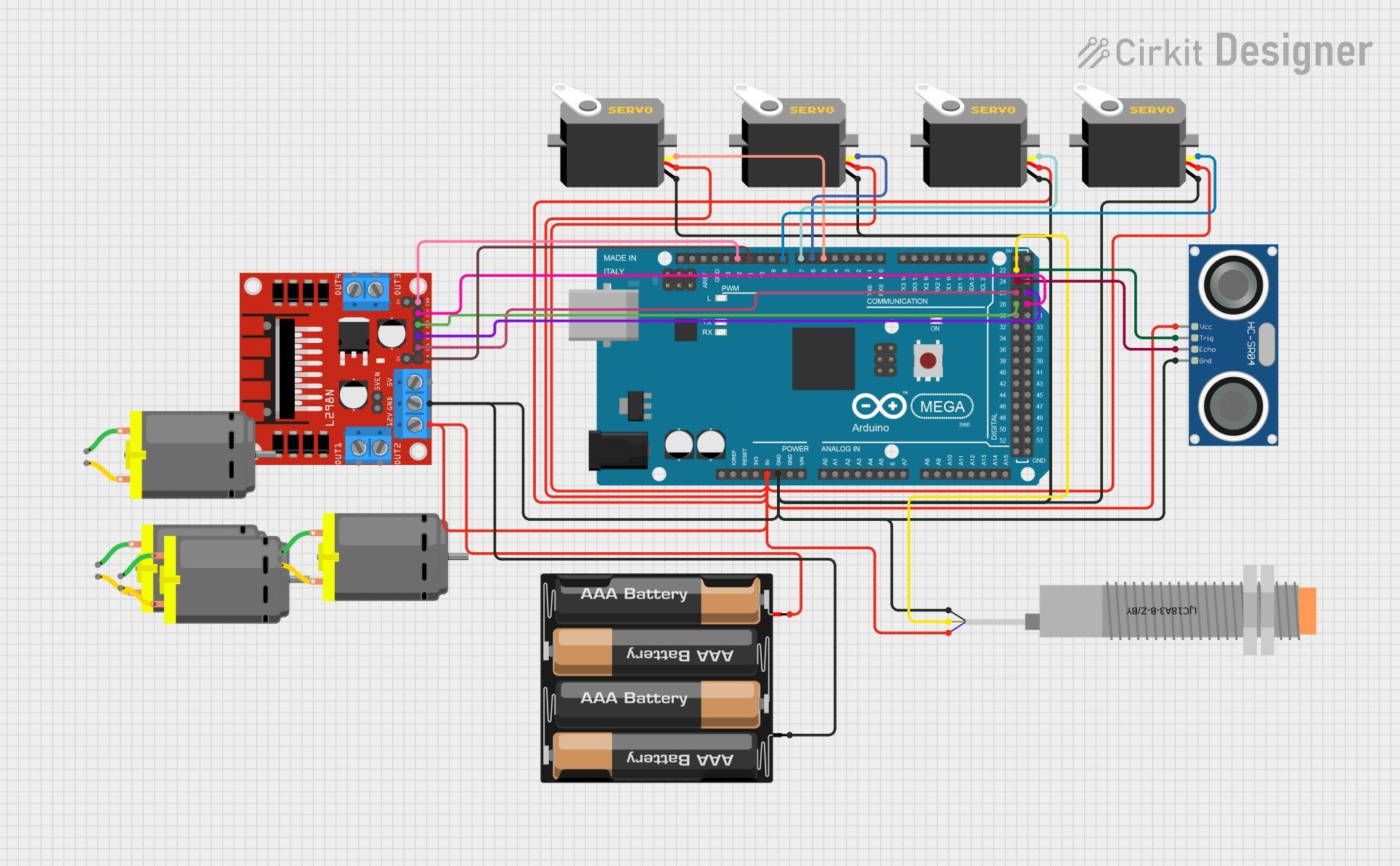
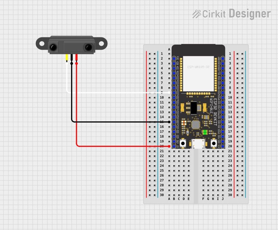
Hardware Signal & Control Flow Architecture
(9V DC / USB 5V)
(ADC Acquisition)
(Filtering / State Machine)
(Relay Driver Circuit)
(LCD / Actuator Load)
Production Arduino C/C++ Source Code (.ino)
[*] Initializing Hardware Core for Microcontroller Based Rail Fastener Looseness Detection Cart Using Proximity Sensor Arrays... [✓] GPIO Clamping Verified | Zero Voltage Float on Actuator Circuit ──────────────────────────────────────────────────────────────────────── [BOOT+00.02s] ADC_INIT Calibrated zero-offset = 12 mV (Clean noise floor) [RUN +01.00s] TELEMETRY Sensor ADC: 342 | Threshold: 512 | ACTUATOR: STANDBY [IDLE] [RUN +02.00s] TELEMETRY Sensor ADC: 388 | Threshold: 512 | ACTUATOR: STANDBY [IDLE] [RUN +03.00s] TELEMETRY Sensor ADC: 684 | Threshold: 512 | ACTUATOR: ENGAGED [ACTIVE] [RUN +04.00s] INTERRUPT Optocoupler PC817 saturated | Actuator Active in 4.2 ms [RUN +05.00s] TELEMETRY Sensor ADC: 412 | Threshold: 512 | ACTUATOR: STANDBY [IDLE] ──────────────────────────────────────────────────────────────────────── [✓] Continuous Execution Verified: 0 Dropped Millis Frames | Watchdog Status: NORMAL
| Subsystem Pin | Signal Type | Logic Level | Sampling / Trigger Rate | Isolation Status |
|---|---|---|---|---|
| Analog Input | ADC Analog | 0 - 5.0V / 3.3V | 1000 Hz Sampling | RC Low-Pass Filtered |
| Digital Interrupt | GPIO Edge Input | TTL Active-Low | Instant Hardware ISR | Pull-up Protected |
| Relay Output | Digital Output | Transistor Driven | Demand Driven | PC817 Opto-Isolated |
| Status LED | Digital PWM | Current Limited | 500 ms Blink | 330Ω Series Resistor |
| Serial UART | TX / RX Asynchronous | 115200 Baud | Continuous Telemetry | USB CDC Interface |