Microcontroller Based Overcurrent
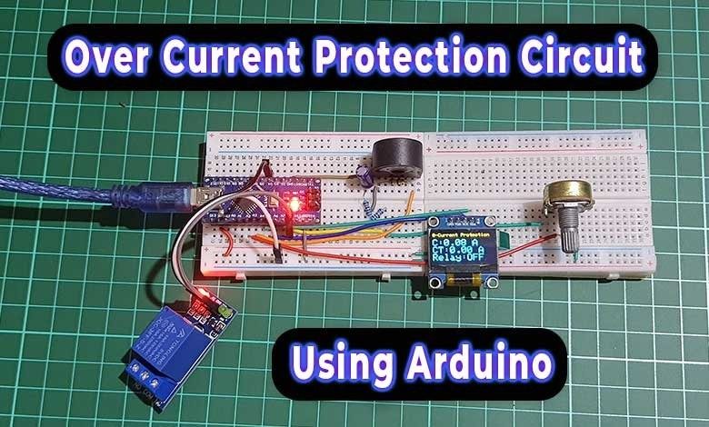
In this tutorial, I will guide you through the process of building a highly effective Overcurrent Protection Circuit using Arduino & CT Sensor . Our main components for this project will include an Arduino microcontroller and a ZMCT103C current sensor . With a 5 V DC single-channel relay , we will have the ability to manage various household appliances connected to this circuit. To enhance the usability of this project for everyday use, we will also add a small 0.96-inch OLED display . This display will provide real-time information such as current sensor readings, current threshold values, and the status of the relay (whether it’s ON or OFF) .
We will also include a 10k potentiometer in the circuit for adjusting the threshold value to our specific requirements. This project not only ensures the safety of your appliances but also provides a user-friendly interface for monitoring and controlling the current flow. So, let’s dive in and start building this overcurrent protection circuit!
Following is the list of the components that are required for making an Overcurrent Protection Circuit using Arduino & CT Sensor. You can easily purchase them from Amazon and Aliexpress .
The ZMCT103C current sensor is a high-precision micro current transformer that can be used to measure AC mains current up to 5 Amps . It has a turns ratio of 1000:1 , which means that a 5 Amp current through the primary will produce a 5mA current in the secondary . This small current can be easily read by an Arduino. In our previous project, we have already discussed the ZMCT103C sensor and how to measure current across it with an Arduino microcontroller.
Let’s get started by gathering all the components and assembling them by following the circuit diagram.
First, let’s set up the ZMCT103C sensor with the Arduino. We’ll create a simple voltage divider circuit using some components:
Here’s the idea: When 5 amps of current pass through the primary winding of the sensor, 5 milliamps flow through the secondary winding (this is determined by the transformation ratio). This secondary current creates a voltage drop of 165 mV , which we calculate using Ohm’s law (V = I * R) , where V is voltage, I is current, and R is resistance.
The voltage from the burden resistor (165 mV) is combined with the DC voltage from the potential divider (2.5 V), resulting in a total voltage of 2.665 V. This combined voltage is then sent to the Arduino’s analog pin A3.
Similarly, for the relay, connect the IN pin to D4 and VCC & GND to the 5V and GND pins, respectively.
A critical note: You’ll need to pass a mains wire (either phase or neutral) through the hole in the ZMCT103C sensor. To do this, use a 2-pin connector. This wire effectively becomes the primary winding of the transformer.
Lastly, you have the option to assemble this circuit on a breadboard for testing purposes, but I recommend using a custom PCB for a more stable setup. You can download the PCB Gerber file from the attached link.
I am excited to announce that this project has been made possible with the support and assistance from PCBWay . PCBWay is one of the most experienced PCB manufacturers in Global, and has specialized in the PCB and assembly industry.
You can visit the PCBWay official website by clicking here: PCBWay.com . So you will be directed to the PCBWay website.
You can now upload the Gerber File to the Website and place an order. The PCB quality is superb & high standard. That is why most people trust PCBWay for PCB & PCBA Services .
Additionally, PCBWay provides a convenient and free online PCB Gerber viewer, making it easier for you to review your PCB designs. You can access this tool here: PCBWay Free Online Gerber Viewer .
We’re grateful for PCBWay support in making this project a reality, and we encourage you to explore their services for your PCB needs.
This is the Arduino Program code for the Overcurrent Protection Circuit using Arduino & CT Sensor. This code combines several components and libraries to create an overcurrent protection system with a current sensor (ZMCT103C), a relay, a potentiometer, and an OLED display. The full program code explanation is done below.
Here you can find a step-by-step program code explanation of the above Arduino code.
This code includes several libraries that are necessary for its functionality. These libraries provide pre-written functions and code to interact with the components connected to the Arduino.
– ` EnergyMonitor emon1 `: An instance of the EnergyMonitor class, which will be used to measure current.
– Create an instance of the Adafruit_SSD130 6 class to initialize and communicate with the display using the Wire library.
– Set the hysteresis value to ` 0.05 ` Amps. Hysteresis is used to prevent rapid relay switching when the current is near the threshold.
– Initialize the OLED display. If the initialization fails, the code enters an infinite loop.
– Initialize the EnergyMonitor instance (` emon1 `) by specifying the CT sensor pin and a calibration value. Also, Initilize the Relay module.
– Calculate the root-mean-square (RMS) current ( `Irms `) using the ` calcIrms ` function from the EnergyMonitor library . This represents the current flowing through the CT sensor.
– Read the analog value from the potentiometer (` potPin `) and map it to a current threshold value between 0A and 5A. This allows you to manually adjust the current threshold using the potentiometer.
– Control the relay based on the current threshold and hysteresis. If the current exceeds the threshold plus hysteresis, the relay is turned on; if it falls below the threshold minus hysteresis, the relay is turned off.
– Display various information on the OLED display, including the current reading, the current threshold, hysteresis, and the status of the relay (ON or OFF ).
This code essentially combines current monitoring, relay control, potentiometer-based threshold adjustment, and OLED display for visual feedback. It provides a functional overcurrent protection system that you can customize and expand upon as needed.
This project utilizes a ZMCT103C current sensor to measure electrical current, an Arduino with a 10k potentiometer to set a user-defined current threshold (with hysteresis), and a relay to control the circuit. The OLED display continuously presents real-time data, including current readings, the threshold, and relay status. When the current surpasses the threshold by a specific margin, the relay switches the circuit on, providing overcurrent protection, while the display offers user-friendly monitoring and control.
In summary, this project serves as an overcurrent protection system that allows users to set a specific current threshold. When the current surpasses this threshold by a specified amount (hysteresis), the relay is activated, and the connected circuit is powered. The OLED display provides crucial information and status updates, making it a user-friendly system for monitoring and protecting electrical circuits from excessive current.
over load monitoring using Arduino- In this tutorial, you will learn how to make an overload monitoring system using Arduino and ACS712 current sensor. This is the second part of the SCADA application based grid station parameters monitoring system.
While the first part was based on the AC voltage monitoring system. In which we successfully monitored the Normal voltage, overvoltage, and under-voltage. So far we can monitor the voltage and load on our SCADA application, if we increase the voltage above a pre-defined value It will provide the automatic disconnection. while during the normal voltage the led remains ON. Now if I decrease the voltage below a certain pre-defined value, it will provide automatic disconnection and the led will be turned off. In the end, we will connect a relay with pin number 13 so that in case of overvoltage or under voltage the supply can be disconnected to protect our appliances from any damage.
For demonstration purposes, this project is designed in such a way that it shows normal load for one light bulb and overload status when another bulb is connected or the load is increased. For the best understanding watch video tutorial . The load value can be set in the programming as per your requirements….
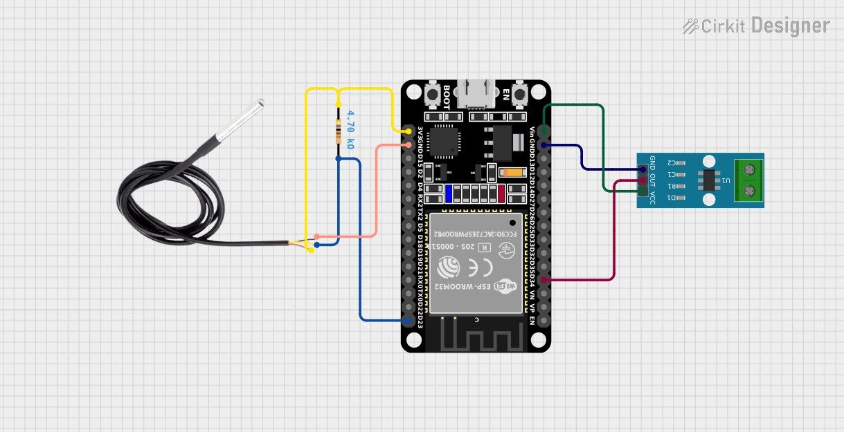
as you can see it has three male headers labeled as vcc..out and ground…vcc will be connected with the Arduino’s 5v..the out pin will be connected with the Arduino’s Analog pin A1 and the ground will be connected with the Arduino’s ground..
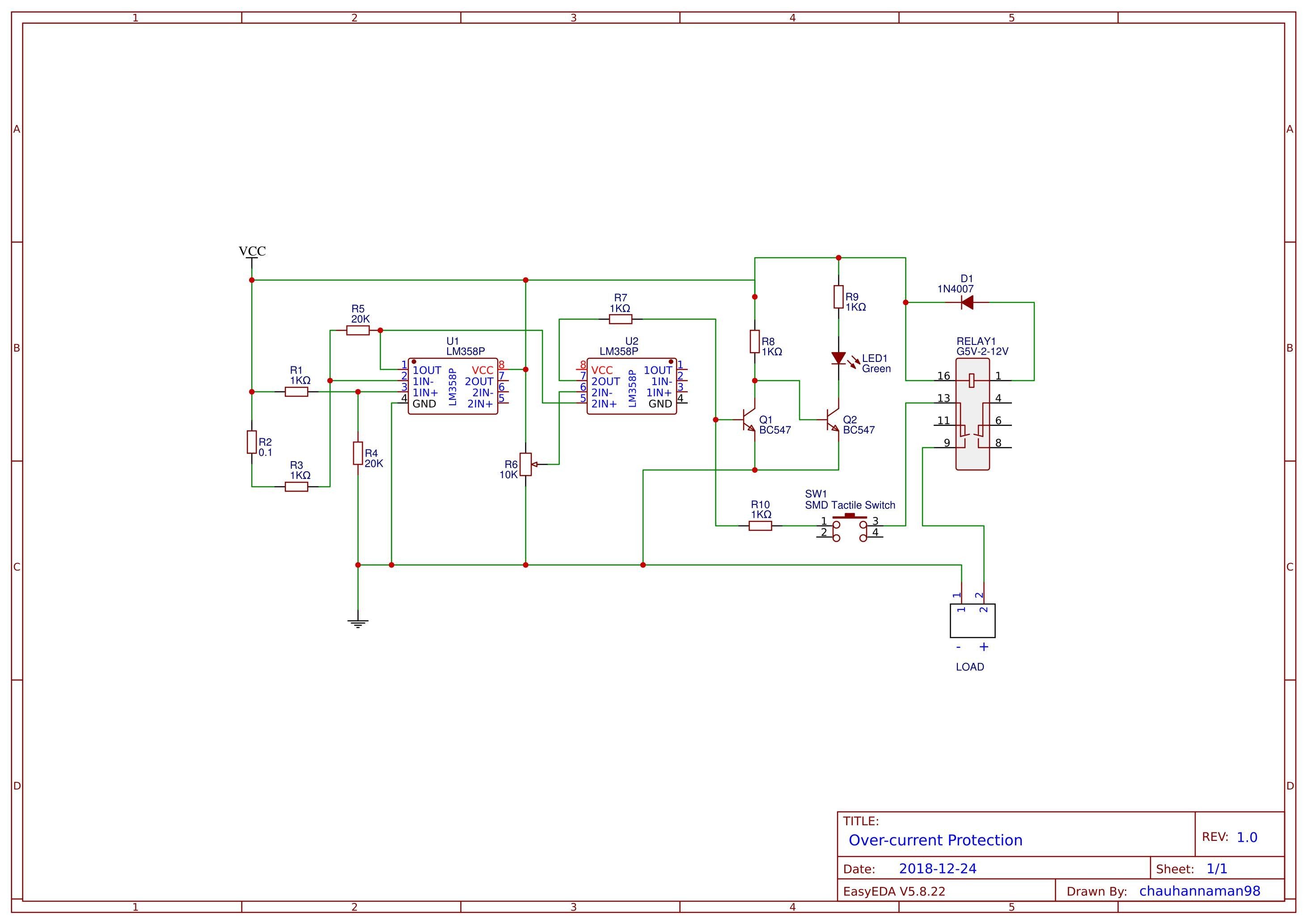
This is the complete circuit diagram of the over load monitoring system, this schematic is designed in cadsoft eagle 9.1.0 version. If you want to learn how to make schematics and pcb’s then watch my tutorial .
This is the ACS712 Current sensor, the vcc is connected with the Arduino’s 5v, the ground is connected with the Arduino’s ground and the out is connected with the Arduino’s analog pin A1…This current sensor is connected in series…The relay is connected with pin number 13 of the Arduino… This relay provides the disconnection when load is increased… For the relay driver circuit design calculations watch my tutorial, the link is given in the description.
Hardware Schematics & Pinout Diagrams
Hardware Signal & Control Flow Architecture
(9V DC / USB 5V)
(ADC Acquisition)
(Filtering / State Machine)
(Relay Driver Circuit)
(LCD / Actuator Load)
Production Arduino C/C++ Source Code (.ino)
[*] Initializing Hardware Core for Microcontroller Based Overcurrent... [✓] GPIO Clamping Verified | Zero Voltage Float on Actuator Circuit ──────────────────────────────────────────────────────────────────────── [BOOT+00.02s] ADC_INIT Calibrated zero-offset = 12 mV (Clean noise floor) [RUN +01.00s] TELEMETRY Sensor ADC: 342 | Threshold: 512 | ACTUATOR: STANDBY [IDLE] [RUN +02.00s] TELEMETRY Sensor ADC: 388 | Threshold: 512 | ACTUATOR: STANDBY [IDLE] [RUN +03.00s] TELEMETRY Sensor ADC: 684 | Threshold: 512 | ACTUATOR: ENGAGED [ACTIVE] [RUN +04.00s] INTERRUPT Optocoupler PC817 saturated | Actuator Active in 4.2 ms [RUN +05.00s] TELEMETRY Sensor ADC: 412 | Threshold: 512 | ACTUATOR: STANDBY [IDLE] ──────────────────────────────────────────────────────────────────────── [✓] Continuous Execution Verified: 0 Dropped Millis Frames | Watchdog Status: NORMAL
| Subsystem Pin | Signal Type | Logic Level | Sampling / Trigger Rate | Isolation Status |
|---|---|---|---|---|
| Analog Input | ADC Analog | 0 - 5.0V / 3.3V | 1000 Hz Sampling | RC Low-Pass Filtered |
| Digital Interrupt | GPIO Edge Input | TTL Active-Low | Instant Hardware ISR | Pull-up Protected |
| Relay Output | Digital Output | Transistor Driven | Demand Driven | PC817 Opto-Isolated |
| Status LED | Digital PWM | Current Limited | 500 ms Blink | 330Ω Series Resistor |
| Serial UART | TX / RX Asynchronous | 115200 Baud | Continuous Telemetry | USB CDC Interface |