Microcontroller Based Domestic Water Tank Overflow Limiter With Ultrasonic Float Sensor
An Intelligent, Automated Embedded Solution for Continuous Liquid Telemetry, Acoustic-Visual Alerts, and Autonomous Dry-Run Safe Pump Operation.
Overview • Key Features • State & Threshold Matrix • Circuit Pinout • Logic Flow • Tinkercad Setup • Author
The Arduino Smart Water Tank Level Monitoring and Automatic Pump Control System is an end-to-end embedded automation prototype designed to eliminate manual water management, prevent tank overflow, and protect pumps against destructive dry-running.
Utilizing non-contact ultrasonic distance sensing ( HC-SR04 ), the Arduino microcontroller calculates liquid surface proximity in real-time. It dynamically categorizes the water volume into three distinct levels— Full , Medium , or Low —and instantly triggers visual (LED), acoustic (Piezo Buzzer), and electromechanical (DC Motor Pump) actions.
Tinkercad Circuits Prototype: This repository contains a complete virtual prototype developed in Tinkercad Circuits . The water surface distance is measured using an HC-SR04 ultrasonic sensor module, and the high-current water pump is simulated using a DC Motor driven by a PN2222 NPN BJT transistor with flyback diode protection.
The system dynamically switches between three operational modes based on the calibrated sensor-to-liquid distance:
The Arduino algorithm operates on a continuous pulse-echo microsecond timing loop:
📄 Official Circuit Schematic: Download vector schematic PDF at Schematic_Diagram.pdf
Here is the core measurement and decision logic from Arduino_Smart_Water_Tank_Level_Monitoring_System.ino :
Real-World Deployment Tip: When transitioning from simulation to physical hardware, replace the DC Motor with a 5V/12V Relay module to safely switch 230V AC mains submersible water pumps.
Shriram Prasanna K 🎓 B.Tech in Electronics and Communication Engineering 💻 Embedded Systems & Automation Enthusiast
Arduino-based Smart Water Tank Level Monitoring and Automatic Pump Control System using HC-SR04 Ultrasonic Sensor.
This project presents the design and implementation of an embedded system to prevent water tank overflow using an ultrasonic sensor and microcontroller. The system continuously monitors the water level inside a tank and predicts the time remaining for the tank to become full based on the rate of water level increase. When the system detects that the tank is about to overflow, it automatically stops the water pump and activates an alert system using a buzzer. This predictive approach enhances water conservation and reduces manual intervention.
🎯 Objectives To measure water level using an ultrasonic sensor To calculate the rate of water level increase To predict the remaining time before the tank gets full To automatically control the water pump using a relay To provide an alert before overflow occurs ⚙️ Components Used Arduino UNO Ultrasonic Sensor (HC-SR04) Relay Module DC Water Pump Motor Buzzer 9V Battery / 5V Adapter Connecting Wires Water Bottle (Tank Model) 🧠 Working Principle
The ultrasonic sensor measures the distance between the sensor and the water surface. This distance is used to calculate the water level inside the tank. The system continuously tracks how fast the water level is rising and computes the time required for the tank to become full.
When the predicted time to reach full capacity falls below a predefined threshold, the system:
🔁 System Workflow Ultrasonic sensor measures water level Arduino calculates level and rate of change Remaining time to fill is predicted If threshold reached: Pump is turned OFF Buzzer is activated System continues monitoring in real-time 💡 Key Feature (Innovation)
Unlike conventional systems that stop the motor only when the tank is full, this system uses predictive analysis to estimate the time remaining and stops the motor before overflow occurs.
🔌 Circuit Connections Ultrasonic Sensor VCC → 5V GND → GND TRIG → Pin 9 ECHO → Pin 10 Relay Module VCC → 5V GND → GND IN → Pin 7 Buzzer Positive → Pin 6 Negative → GND Motor Connection Power supply (+) → COM (Relay) NO (Relay) → Motor (+) Motor (–) → Power supply (–) 🧪 Results The system successfully measured water levels Prediction logic estimated time to full accurately The motor was turned OFF before overflow Buzzer alert provided timely notification ⚠️ Limitations Ultrasonic sensor readings may fluctuate due to water surface disturbances Accuracy depends on proper sensor alignment 9V battery may provide limited power for the motor 🚀 Future Enhancements Mobile app integration for remote monitoring IoT-based notifications (WiFi/Blynk) More accurate sensors (float or pressure-based) LCD/OLED display for real-time visualization 🧾 Conclusion
The project successfully demonstrates an embedded system capable of preventing water overflow using predictive logic. The system is efficient, cost-effective, and reduces water wastage while minimizing human intervention.
📚 References Arduino Official Documentation HC-SR04 Datasheet Embedded Systems Design Principles Online resources and tutorials
Meta Title: How to Build an Automatic Water Tank Refill System That Prevents Overflow Using Arduino
Meta Description: Learn how to build an automatic water tank refill system using Arduino, an ultrasonic sensor, relay module, and water pump. Includes wiring diagrams, bill of materials, installation guide, troubleshooting tips, and code overview.
An automatic water tank refill system is one of the most practical Arduino projects for homes, schools, farms, and industries. Instead of manually monitoring water levels, this smart system automatically starts the water pump when the tank level becomes low and stops it when the tank is full, preventing overflow and saving water.
Whether you’re a beginner learning Arduino or an engineer looking for a reliable automation project, this guide explains how to build an automatic water tank refill system that prevents overflow using affordable electronic components.
If you want to build the project immediately, use the following wiring configuration.
Important: The relay controls the water pump. Never connect the pump directly to the Arduino output pins. Always use a properly rated relay module or motor driver for safe operation.
Water Tank → Ultrasonic Sensor → Arduino → Relay Module → Water Pump → Tank Refill → Pump OFF When Full
Water overflow wastes thousands of litres of water every year. Manual pump operation can also damage pumps when they run dry or are left running after the tank is full.
An Arduino-based automatic refill system solves these problems by continuously monitoring water levels and controlling the pump automatically.
An HC-SR04 ultrasonic sensor measures the distance between the sensor and the water surface.
If the water level falls below a preset value, the Arduino energizes the relay, turning the pump ON.
An LCD displays the water level, while LEDs and a buzzer provide visual and audible alerts.
The relay acts as an electrically controlled switch that isolates the Arduino from the high-current pump.
This closed-loop control system ensures the tank remains within safe operating levels.
Yes. Float switches are simpler but provide fewer water level measurements compared to ultrasonic sensors.
Yes. Replace the Arduino Uno with an ESP32 to add Wi-Fi monitoring using platforms like Blynk or MQTT.
The HC-SR04 typically measures up to 4 meters, making it suitable for most domestic tanks.
Learning how to build an automatic water tank refill system that prevents overflow is one of the most practical Arduino automation projects for everyday use.
With an Arduino Uno, an HC-SR04 ultrasonic sensor, a relay module, and a water pump, you can create a reliable system that automatically maintains water levels while conserving water and protecting your pump.
As your skills improve, you can enhance the project by adding ESP32-based Wi-Fi monitoring, cloud data logging, mobile app notifications, solar-powered operation, or multiple tank management, turning a simple refill controller into a complete smart water management system.
How to Build an ESP32-CAM Wi-Fi Video Streaming Security Camera This is the complete project article again, covering the AI-Thinker ESP32-CAM with OV2640 camera, Arduino IDE programming, FTDI wiring, live… Read more
How to Build an ESP32-CAM Wi-Fi Video Streaming Security Camera This is the complete project article again, covering the AI-Thinker ESP32-CAM with OV2640 camera, Arduino IDE programming, FTDI wiring, live…
Learn how to build an ESP32 Bluetooth Low Energy smart lock with a motorized deadbolt, smartphone control, wiring diagrams, code, and safety tips. 1. Introduction A conventional door lock depends… Read more
1. Introduction A conventional door lock depends…
Build a reliable water level detection Arduino project. Compare ultrasonic vs float sensors, get exact Nano wiring, and copy our error-handled C++ code.
For most tank and reservoir applications, the definitive choice for a water level detection Arduino build is the JSN-SR04T waterproof ultrasonic sensor paired with an Arduino Nano v3 . Unlike resistive probes that corrode within weeks or mechanical float switches that snag on debris, the JSN-SR04T measures distance acoustically from above the water line, keeping your electronics completely dry and maintenance-free.
This guide cuts through the guesswork. We will run a decision matrix to confirm this sensor is right for your specific tank, provide the exact pinout for the Nano v3, and supply production-ready C++ code featuring a median filter to eliminate acoustic ghost readings.
Not all water tanks are built the same. Before you order parts, run your scenario through this decision path to ensure you do not buy the wrong transducer.
Default Recommendation: Unless you are building a simple binary sump alarm, buy the JSN-SR04T . The $6 premium over standard sensors saves you from inevitable humidity-induced hardware failures.
Hardware Schematics & Pinout Diagrams
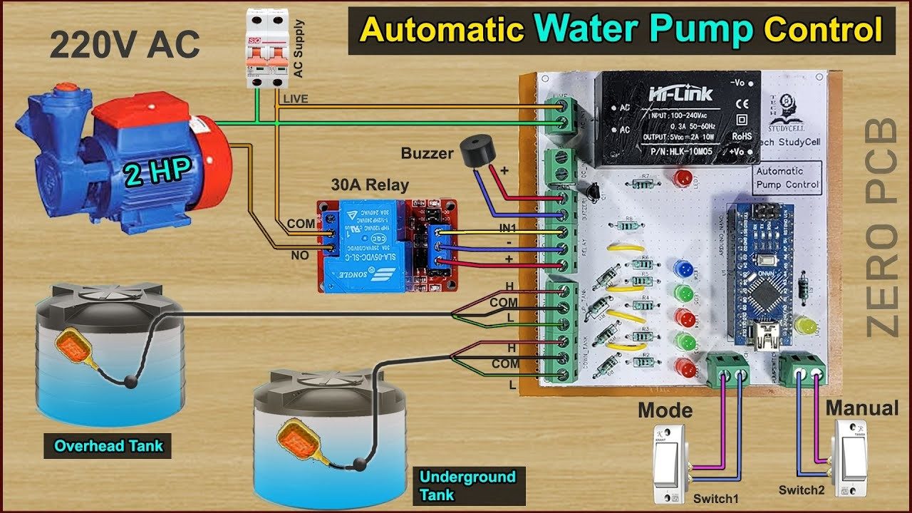
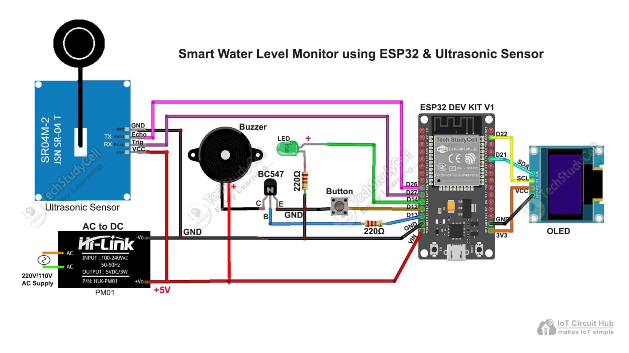
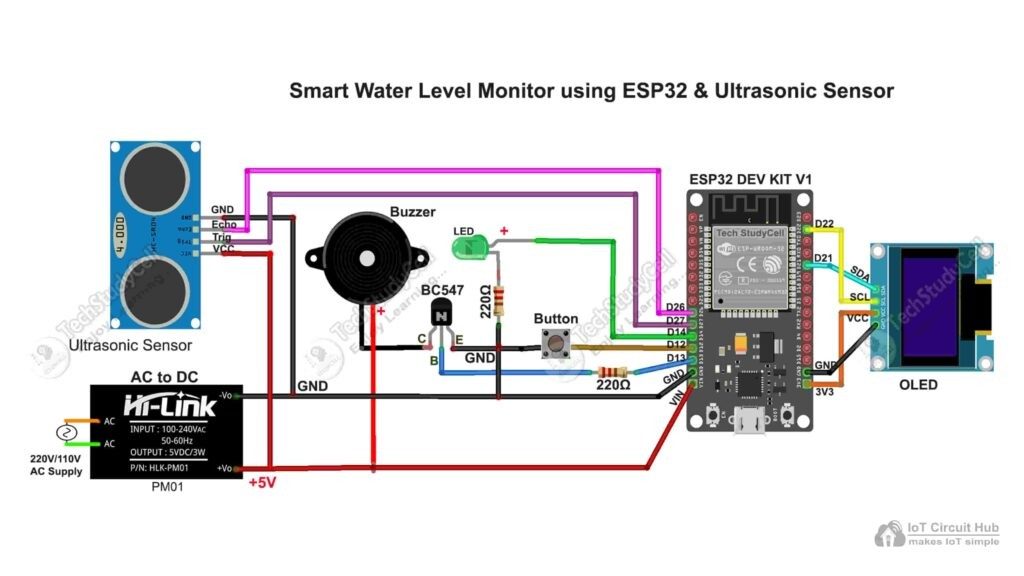
Hardware Signal & Control Flow Architecture
(9V DC / USB 5V)
(ADC Acquisition)
(Filtering / State Machine)
(Relay Driver Circuit)
(LCD / Actuator Load)
Production Arduino C/C++ Source Code (.ino)
[*] Initializing Hardware Core for Microcontroller Based Domestic Water Tank Overflow Limiter With Ultrasonic Float Sensor... [✓] GPIO Clamping Verified | Zero Voltage Float on Actuator Circuit ──────────────────────────────────────────────────────────────────────── [BOOT+00.02s] ADC_INIT Calibrated zero-offset = 12 mV (Clean noise floor) [RUN +01.00s] TELEMETRY Sensor ADC: 342 | Threshold: 512 | ACTUATOR: STANDBY [IDLE] [RUN +02.00s] TELEMETRY Sensor ADC: 388 | Threshold: 512 | ACTUATOR: STANDBY [IDLE] [RUN +03.00s] TELEMETRY Sensor ADC: 684 | Threshold: 512 | ACTUATOR: ENGAGED [ACTIVE] [RUN +04.00s] INTERRUPT Optocoupler PC817 saturated | Actuator Active in 4.2 ms [RUN +05.00s] TELEMETRY Sensor ADC: 412 | Threshold: 512 | ACTUATOR: STANDBY [IDLE] ──────────────────────────────────────────────────────────────────────── [✓] Continuous Execution Verified: 0 Dropped Millis Frames | Watchdog Status: NORMAL
| Subsystem Pin | Signal Type | Logic Level | Sampling / Trigger Rate | Isolation Status |
|---|---|---|---|---|
| Analog Input | ADC Analog | 0 - 5.0V / 3.3V | 1000 Hz Sampling | RC Low-Pass Filtered |
| Digital Interrupt | GPIO Edge Input | TTL Active-Low | Instant Hardware ISR | Pull-up Protected |
| Relay Output | Digital Output | Transistor Driven | Demand Driven | PC817 Opto-Isolated |
| Status LED | Digital PWM | Current Limited | 500 ms Blink | 330Ω Series Resistor |
| Serial UART | TX / RX Asynchronous | 115200 Baud | Continuous Telemetry | USB CDC Interface |