Microcontroller Based Digital Lockout Tagout Loto Key Exchange Safety Cabinet
Our 5G IoT smart padlocks and APIs provide an online solution to enhance safety, efficiency, and effectiveness in LOTO processes.
Lockout-tagout (LOTO) is a widely used safety procedure across various industries worldwide to ensure the safe shutdown of hazardous machinery or equipment before maintenance, repair, or cleaning work is performed. This is done to protect workers from potential hazards, accidents, and injuries. LOTO procedures involve several steps and reporting requirements which are mandatory for most industries, including manufacturing, construction, utilities, transportation, chemical processing, mining, healthcare, and more. Employers are responsible for identifying situations where LOTO procedures are necessary and implementing them to protect their workers while adhering to relevant regulations and standards.
In the United States, the Occupational Safety and Health Administration (OSHA) is responsible for enforcing workplace safety and health standards including LOTO procedures. Inspectors from OSHA or state agencies often visit workplaces to assess LOTO programs and procedures and ensure employers comply with regulations.
Although LOTO procedures are effective in preventing workplace accidents and injuries, they also present many challenges often bringing significant downtime and loss of productivity to companies. Most of the LOTO procedure is manual with heavy human involvement (little or no electronic automations or processes exist). Therefore human error and time wasting is an ongoing challenge, as employees implementing LOTO procedures must be cautious and diligent. The procedures themselves are also complex and often take several hours, leading to confusion and errors. Additionally, some employees or companies may bypass the LOTO procedure to save time, potentially putting themselves and others at risk. Proper training and communication are crucial for effective LOTO procedures too.
Several types of mechanical locks are used in LOTO procedures depending on the energy source being locked out - typically metal key padlocks, combination padlocks, cable locks, hasp locks, ball valve locks, and breaker locks are used.
Digital Keys are working with several manufacturing companies to implement our 5G IoT smart padlocks and API’s into an effective online solution for enhancing the safety, efficiency, and effectiveness of the Lockout/Tagout (LOTO) process. Our connected smart padlocks allow greater control, accuracy, reporting and flexibility over metal key padlocks. With the Digital Keys API's, the smartlocks are integrated with maintenance management, scheduling and notification systems, automating the LOTO process and reducing the risk of human errors or oversights. For instance, smart locks can be programmed to grant access only to authorized personnel, and access can be granted or revoked remotely, reducing the waiting time for specialized trained personnel to be physically present to coordinate the process.
Moreover, our 5G IoT smart padlocks provide real-time monitoring and reporting of the LOTO process by enabling managers and supervisors to monitor who has accessed the lock and when, and track compliance with LOTO procedures. In case someone attempts to access a locked-out energy source, the smartlock's inbuilt vibration sensors detect movement and send an immediate alert to the appropriate personnel. All this data is recorded and used in big data analytics and with AI tools to identify common issues or hazards, and constantly suggest more ways for improvement.
Using our 5G IoT smart padlocks also eliminates the need for physical keys and associated paperwork, reducing the risk of lost or misplaced keys. This makes the LOTO process faster and more efficient, reducing downtime, improving productivity and ultimately saving companies significant time and money. For example, employees will no longer need to fill out the Lockout/Tagout Log and tags by hand to track the use of locks during LOTO procedures. The date, time, location of the lockout, the equipment being locked out, and the names of the employees no longer need to be written down in a book, and is instead automatically recorded in the online system and stored in the cloud database. The verification step, where employees go around to all the machines locked out on the factory floor, is also removed and automated with essentially the smartlocks themselves 'reporting their live status'. This system automatically confirms that all energy sources have been correctly locked out and cannot be restarted, making the LOTO process even safer.
The safety of employees and the prevention of accidents are paramount in a typical LOTO procedure, which involves following a series of carefully prescribed steps. These steps are currently performed with significant human involvement and can take anywhere from 15 minutes for one basic machine to several hours or even days for very complex machinery. This process results in significant downtime and loss of productivity for companies. While this short-term downtime is necessary to prevent accidents, injuries, and damage to equipment, which can ultimately result in longer periods of downtime, higher costs, and potential legal liabilities for the company, it is often completed meticulously and without rushing. The LOTO procedure can be improved and made more efficient by automating most of the LOTO procedure steps with 5G IoT locks and associated online systems, reducing downtime and productivity without sacrificing safety.
Digitizing the LOTO procedure with 5G IoT smartlocks and integrating associated online systems and software is also about reducing human errors in the steps involved, ultimately reducing workers' exposure to serious hazards and injuries caused by unexpected energization, start-up, or release of stored energy. This approach can achieve reductions in exposure to electrical shock, which can cause burns, heart damage, and even death. Additionally, crushing injuries can be reduced. For example, if a worker is working on or near machinery that is not properly locked out, it can start up unexpectedly and cause broken bones, cuts, amputations, and internal injuries. More efficient LOTO procedures can also reduce the risk of explosions from machines with flammable gases or liquids, which results in burns, broken bones, and other injuries.
Digital Keys cloud-based 5G IoT smart access control systems, including smart locks and APIs, improves security, safety, and efficiencies of mine sites while not requiring onsite mains power or equipment.
Electricity companies are seeking connected electronic access control solutions with smart locks, digital keys and tampering alarms that are versatile enough to fit into various boxes and cabinets
The logistics industry faces various challenges, including security and tracking issues with shipping containers. 5G IoT smart padlocks aim to address these challenges.
LOTO is critical and complex, but businesses have new technology solutions to ensure compliance and safety. What’s involved?
Lockout/Tagout (LOTO) is an essential set of procedures are critical to safeguarding workers from hazardous energy during maintenance and servicing activities.
OSHA mandates the use of LOTO practices to prevent the unexpected startup or release of stored energy that can result in severe injuries or fatalities. According to OSHA’s standards (29 CFR 1910.147), LOTO procedures must be implemented whenever workers are exposed to machinery or equipment that could unexpectedly energize, start up, or release hazardous energy, putting them at risk of serious harm.
LOTO protects workers by ensuring that machinery or equipment remains fully de-energized and secured during maintenance or servicing. This process prevents accidental startup and controls various types of hazardous energy sources, including electrical, hydraulic, pneumatic, mechanical, and thermal energy. Without LOTO, workers are vulnerable to severe injuries, such as electrocution, crushing, burns, and amputations.
In OSHA-compliant LOTO, equipment must be shut off and disconnected from its energy sources before any work is performed. Employees must apply locks and tags to control these energy sources and verify the isolation before beginning work. Also, only authorized personnel are permitted to remove locks, ensuring that only trained individuals can manage hazardous energy safely.
However, LOTO methods rely on physical locks, tags, and manual documentation, which, while effective, can lead to inefficiencies and potential errors, especially in large-scale or high-risk operations. Ensuring compliance can get particularly knotty in large facilities or operations with intricate machinery and multiple energy sources.
Not surprisingly, companies recognize the need to modernize their LOTO processes can streamline safety procedures, improve efficiency, and reduce the risk of accidents, making innovative approaches a valuable asset in today’s demanding safety landscape. So, digital solutions have emerged to help facilitate streamlined, accountable, and data-driven safety practices. By integrating digital tools, such as mobile applications, real-time dashboards, and tamper-resistant locks, companies can create safer environments and simplify compliance with regulatory requirements.
The latest innovation: Connected LOTO. Connected LOTO systems incorporate a combination of Internet of Things (IoT) devices, mobile applications, cloud platforms, and real-time data analytics to enhance safety and efficiency. Some key elements of connected LOTO:
This article originally appeared in the November/December 2024 issue of Occupational Health & Safety.
The industry's thinnest cut protection, offering maximum tactility and mobility for extreme precision work.
Training gaps, load blind spots, plant noise, cramped layouts and deferred maintenance put forklift operators and pedestrians at risk in heavy industrial plants. Read Now
OSHA's proposal to drop required medical evaluations for N95 and loose-fitting PAPR users could ease paperwork, but it also raises questions about screening, program consistency and worker health. Read Now
Good shoe tread does more than prevent slips. It gives workers the grip they need to push carts, pull loads and reach safely without losing their footing. Read Now
Hardware Schematics & Pinout Diagrams
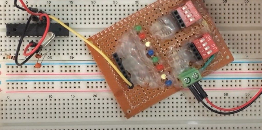
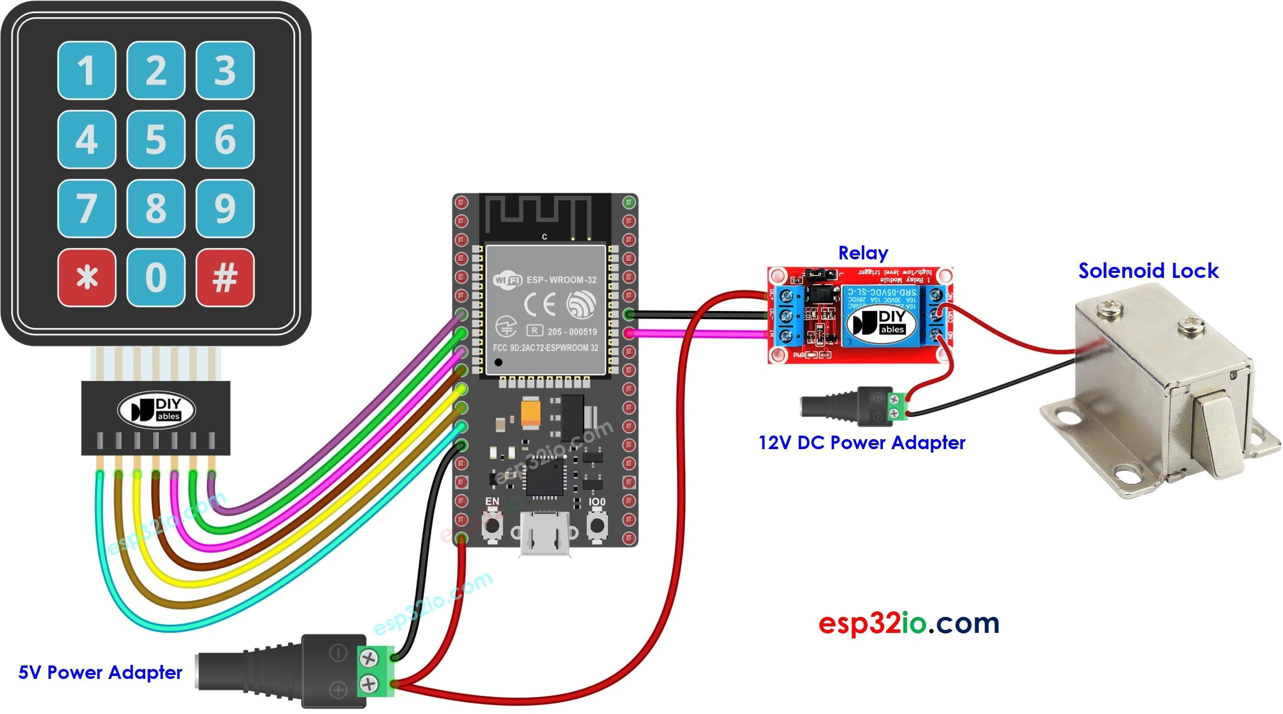
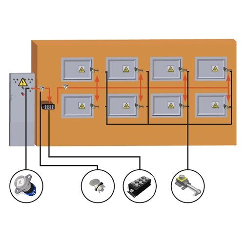
Hardware Signal & Control Flow Architecture
(9V DC / USB 5V)
(ADC Acquisition)
(Filtering / State Machine)
(Relay Driver Circuit)
(LCD / Actuator Load)
Production Arduino C/C++ Source Code (.ino)
[*] Initializing Hardware Core for Microcontroller Based Digital Lockout Tagout Loto Key Exchange Safety Cabinet... [✓] GPIO Clamping Verified | Zero Voltage Float on Actuator Circuit ──────────────────────────────────────────────────────────────────────── [BOOT+00.02s] ADC_INIT Calibrated zero-offset = 12 mV (Clean noise floor) [RUN +01.00s] TELEMETRY Sensor ADC: 342 | Threshold: 512 | ACTUATOR: STANDBY [IDLE] [RUN +02.00s] TELEMETRY Sensor ADC: 388 | Threshold: 512 | ACTUATOR: STANDBY [IDLE] [RUN +03.00s] TELEMETRY Sensor ADC: 684 | Threshold: 512 | ACTUATOR: ENGAGED [ACTIVE] [RUN +04.00s] INTERRUPT Optocoupler PC817 saturated | Actuator Active in 4.2 ms [RUN +05.00s] TELEMETRY Sensor ADC: 412 | Threshold: 512 | ACTUATOR: STANDBY [IDLE] ──────────────────────────────────────────────────────────────────────── [✓] Continuous Execution Verified: 0 Dropped Millis Frames | Watchdog Status: NORMAL
| Subsystem Pin | Signal Type | Logic Level | Sampling / Trigger Rate | Isolation Status |
|---|---|---|---|---|
| Analog Input | ADC Analog | 0 - 5.0V / 3.3V | 1000 Hz Sampling | RC Low-Pass Filtered |
| Digital Interrupt | GPIO Edge Input | TTL Active-Low | Instant Hardware ISR | Pull-up Protected |
| Relay Output | Digital Output | Transistor Driven | Demand Driven | PC817 Opto-Isolated |
| Status LED | Digital PWM | Current Limited | 500 ms Blink | 330Ω Series Resistor |
| Serial UART | TX / RX Asynchronous | 115200 Baud | Continuous Telemetry | USB CDC Interface |