Microcontroller Assisted Solar Charging Station With Supercapacitor Buffer For Fast Delivery Drones
So in this article we are trying to make a true MPPT solar charger project using Arduino which will charge a 12V battery from a solar panel and will use MPPT logic to always extract maximum power from the solar panel. That means that even when sunlight changes, we try to adjust PWM duty cycle smartly so that the panel gives out optimum wattage all the time, not wastefully.
We know that solar panel has one sweet spot where it gives max wattage. That spot changes if sunlight goes up or down. So we need to track that spot using code. That method is called Perturb and Observe (P&O). It means that we change duty cycle slightly and observe if power increased or decreased. If it increased then we go more in that direction. If it reduced then we go back. Very simple.
We also want a manual override. That means user can stop MPPT and use fixed duty cycle if needed. So we use a switch connected to digital pin, if it is LOW = auto mode (MPPT running), if HIGH = manual mode (fixed PWM).
We show all info on LCD: solar volts, current, power, PWM duty, mode, etc. So we know what is going on live.
We use analogWrite (fast PWM pin) to generate switching signal to buck MOSFET. We can also use Timer1 library if more accuracy is needed later.
MOSFET drain to solar panel positive (input), source to inductor input, inductor output to battery +ve.
For calculating the inductor value, you can take the help of this buck converter calculator.
In the MOSFET buck converter stage, we do the connections in the following manner:
We take the solar panel positive , give it to the drain of the MOSFET . Then the source of MOSFET goes to the inductor input . After the inductor we connect to battery +ve . The MOSFET source side also connects with one side of flyback diode and its other side goes to battery -ve . That way when MOSFET turns OFF then diode gives path for inductor to dump energy into battery.
We use pins D4 to D9 for LCD. A 10k preset is needed between +5V, GND, and LCD pin 3 to adjust contrast.
In the code, you can switch between ACS712 or INA219 by changing the flag useINA219 = true; or false; .
hello swagatam… pls do you have an article on good explaination on how mppt charge controller works or explanation on how it make vmp and Imp steady and how it keep adjusting duty cycle for perturb and observe?I really want to understand this this and see how I can implement it my self.
Hi David, I have the following couple of articles which discuss the same concepts which you are interested in, please check them out and let me if this helps or not: https://www.homemade-circuits.com/real-mppt-solar-charger-circuit-using-arduino-lcd-and-manual-auto-switch/
https://www.homemade-circuits.com/true-mppt-solar-controller-circuit-using-ic-555/
please assist me with block diagram of this project. I am now modifying this project
I’m talking about real MPPT Solar Charger Circuit Using Arduino, LCD, current sensor and Manual/Auto Switch. hints; block diagram, flow chart and connection part of buck converter. and also if you have hardware connection on YouTube, then share for the link.
Here is the block diagram, I can only provide the block diagram and the schematic:
yes this article talks about it but I really don’t understand how the duty cycle changes when doing P&O. does the duty cycle change intensionally to check if power is increased and the continue changing in that direction? then again let’s say I have a panel of different parameters but same power can it still be used ? or what if I want to use a high power panel without changing the voltage and current sensor?
In P&O we basically keep pushing the duty cycle a little purposely just to see that if then the panel power goes up or goes down. So now if the power increases then we keep moving in that same direction, but if the power drops then we reverse the step and move the other way. That is why you see the duty cycle changing all the time.
About different panel parameters, as long as the panel can give the same or more watt, then the MPPT will still lock on the peak point automatically, so that is fine. But if the panel watt is very high and you use the same voltage and current sensors, then those sensors must handle that max voltage and current. If they cannot, then you have to upgrade the divider or the sensor rating, otherwise the readings will saturate and the MPPT will not work correctly.
okay,but how do I implement a CCCV alogrithm to it for just one signal pwm if I would be using a synchronous buck converter method,like since mppt changes the duty cycle often, won’t they be an error if adjusting the duty cycle for cv mode and cc mode
Yes, in that case I think it is better to control the CC, CV actions through external analogue cut-off circuits, what do you think?
ok yes…after some thinking, I realize that a two stage buck converter can be actually cheaper and avoid MPPT entirely….and also equally efficient.
The two-stage idea looks valid and simple from a control perspective but you can avoid extra hardware by letting the MCU run MPPT while a faster CC/CV inner loop (software or hardware) clamps the PWM and pause MPPT when CC/CV is active. Analog cut-offs are also good as fail-safe, but maybe not as the only control.
Hi ,Dear By using N Channel causing very heat up issue rather than using P channel ,
Sure Dear, If you want to use a P-channel MOSFET, then you may have to reverse the PWM action by adding an inverting BC547 transistor between the MOSFET gate and the Arduino output…
Thanks a lot , Actually iam using N-Channel Mosfet , even 10 mosfet like irf1407 become heated on only 4 Amps load i read some where that by using N- channel mosfet in the high side configruation causing fets heat up issue which is due to the nearlly the same voltage on both drain and gate here small current flows due to deference between source and gate that’s why the resistance of mosfet become high the mosfet become heated, for this it required voltage boost required for this deference between source and gate is this true ?
Yes, what you have heard is true. I will update the circuit diagram soon with a P channel mosfet
Discover the best solar powered Arduino setups, community guides, and MPPT charge controllers for off-grid IoT nodes in 2026. Build reliable low-power projects.
As the maker community pushes deeper into remote environmental monitoring, decentralized mesh networks, and off-grid agriculture, the demand for a reliable solar powered Arduino setup has never been higher. In 2026, we are no longer just blinking LEDs on breadboards; we are deploying nodes in harsh environments where swapping batteries is impossible. However, simply wiring a 6V solar panel to a charge controller and hoping for the best is a recipe for node failure. True off-grid reliability requires a deep understanding of microcontroller sleep states, power management integrated circuits (PMICs), and battery chemistry.
This community resource roundup synthesizes the most successful open-source hardware configurations, field-tested charge controllers, and troubleshooting frameworks used by advanced makers and IoT engineers today.
The biggest mistake beginners make when building a solar powered Arduino project is selecting a microcontroller based on processing power rather than its deep sleep current. When a node sleeps for 23 hours a day, the baseline quiescent current dictates your battery sizing and panel requirements.
As documented in the official Espressif Sleep Modes API , the ESP32-S3 remains a community favorite due to its balance of low deep-sleep current and high-throughput WiFi capabilities. However, to achieve the advertised 10 µA, you must explicitly power down the RTC peripheral domain and isolate GPIO pins to prevent leakage currents.
The bridge between your solar panel and your battery is the charge controller. In 2026, the community has largely standardized around three tiers of power management, depending on budget and panel size.
Available for $3 to $5 on global marketplaces, the CN3791 is a Pulse Width Modulation (PWM) solar charge controller. It is rugged, simple, and works well with 5W+ panels. However, PWM controllers pull the panel voltage down to match the battery voltage, wasting up to 20% of potential energy. It is acceptable for high-sun environments but inefficient for indoor or heavily shaded deployments.
Hardware Schematics & Pinout Diagrams
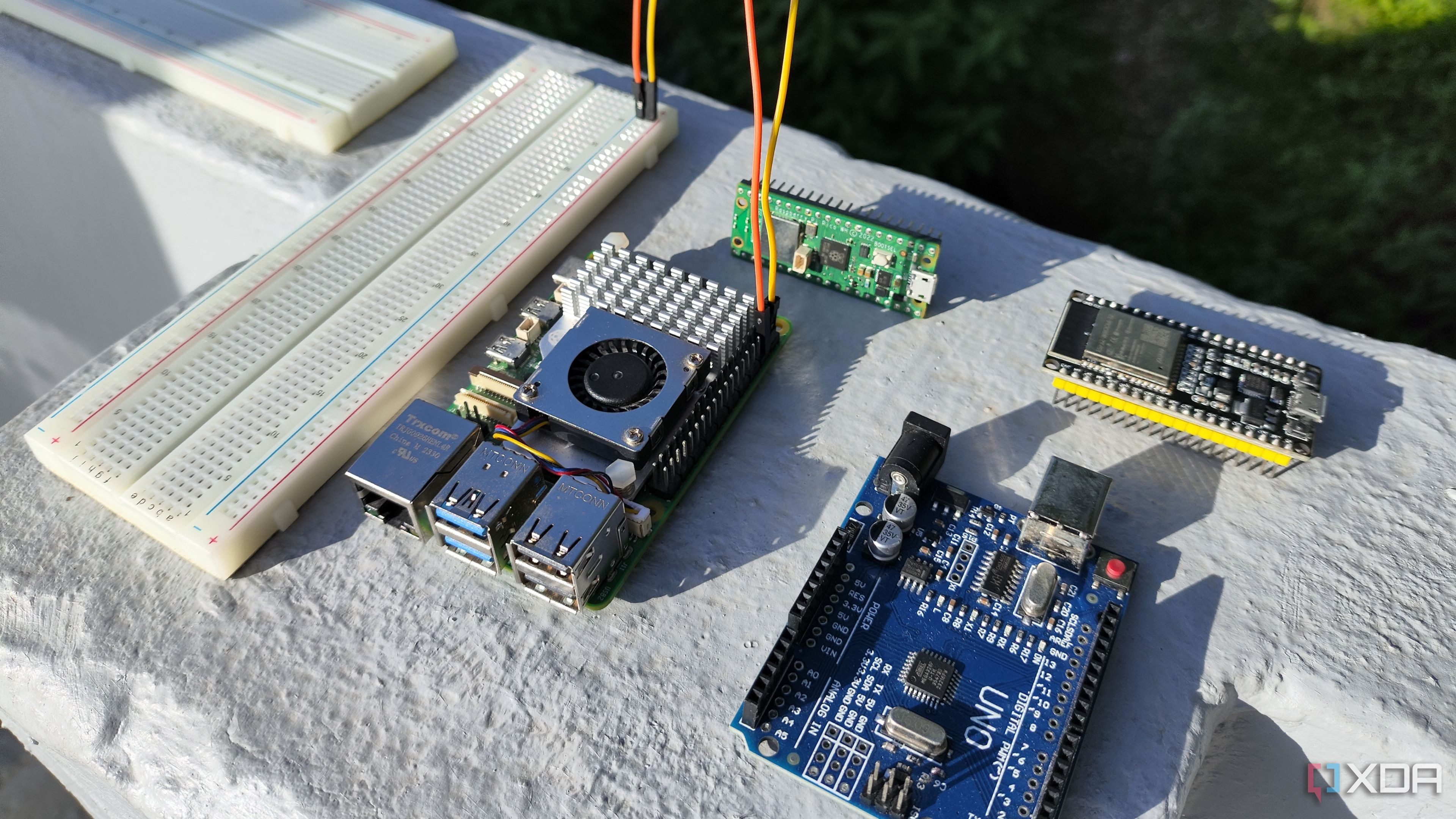
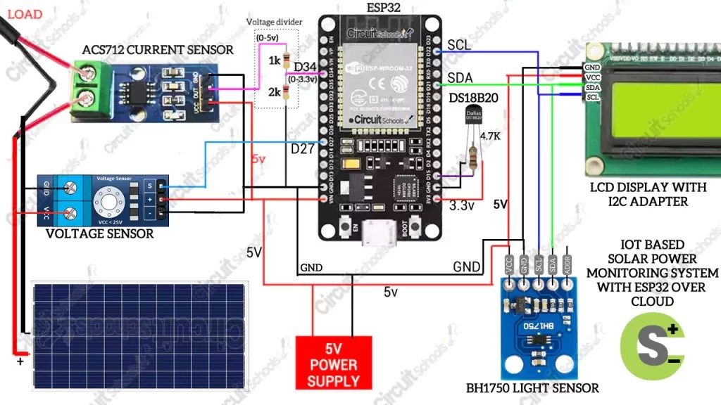
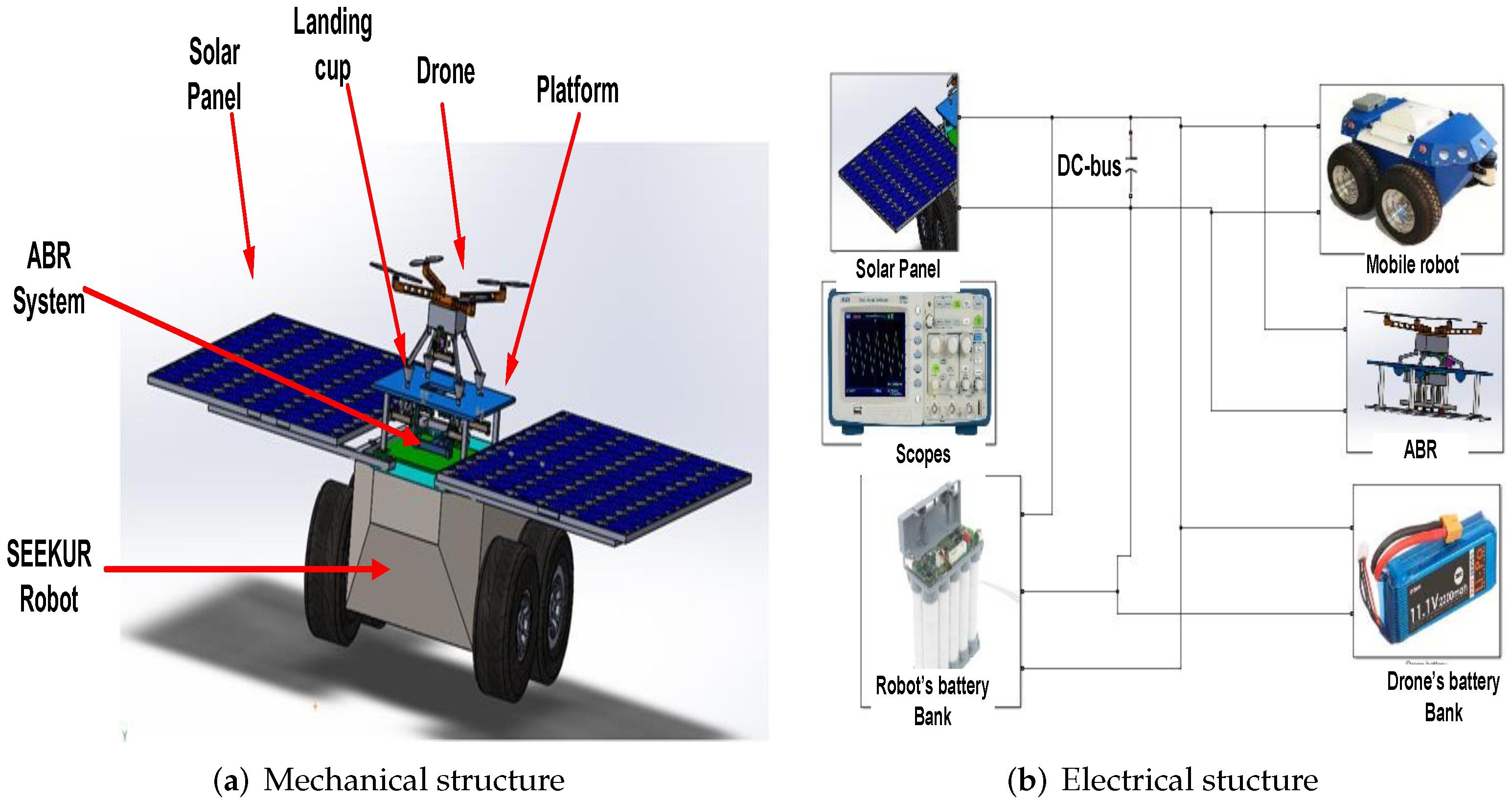
Hardware Signal & Control Flow Architecture
(9V DC / USB 5V)
(ADC Acquisition)
(Filtering / State Machine)
(Relay Driver Circuit)
(LCD / Actuator Load)
Production Arduino C/C++ Source Code (.ino)
[*] Initializing Hardware Core for Microcontroller Assisted Solar Charging Station With Supercapacitor Buffer For Fast Delivery Drones... [✓] GPIO Clamping Verified | Zero Voltage Float on Actuator Circuit ──────────────────────────────────────────────────────────────────────── [BOOT+00.02s] ADC_INIT Calibrated zero-offset = 12 mV (Clean noise floor) [RUN +01.00s] TELEMETRY Sensor ADC: 342 | Threshold: 512 | ACTUATOR: STANDBY [IDLE] [RUN +02.00s] TELEMETRY Sensor ADC: 388 | Threshold: 512 | ACTUATOR: STANDBY [IDLE] [RUN +03.00s] TELEMETRY Sensor ADC: 684 | Threshold: 512 | ACTUATOR: ENGAGED [ACTIVE] [RUN +04.00s] INTERRUPT Optocoupler PC817 saturated | Actuator Active in 4.2 ms [RUN +05.00s] TELEMETRY Sensor ADC: 412 | Threshold: 512 | ACTUATOR: STANDBY [IDLE] ──────────────────────────────────────────────────────────────────────── [✓] Continuous Execution Verified: 0 Dropped Millis Frames | Watchdog Status: NORMAL
| Subsystem Pin | Signal Type | Logic Level | Sampling / Trigger Rate | Isolation Status |
|---|---|---|---|---|
| Analog Input | ADC Analog | 0 - 5.0V / 3.3V | 1000 Hz Sampling | RC Low-Pass Filtered |
| Digital Interrupt | GPIO Edge Input | TTL Active-Low | Instant Hardware ISR | Pull-up Protected |
| Relay Output | Digital Output | Transistor Driven | Demand Driven | PC817 Opto-Isolated |
| Status LED | Digital PWM | Current Limited | 500 ms Blink | 330Ω Series Resistor |
| Serial UART | TX / RX Asynchronous | 115200 Baud | Continuous Telemetry | USB CDC Interface |