Microcontroller Assisted Glacier Ice Melt Velocity Tracker Using Sub Surface Wire Potentiometers
Reliance on expensive and proprietary commercial data acquisition and telemetry systems can present a barrier to monitoring remote polar environments. The development of low-cost, open-source instrumentation can greatly reduce the cost of research in remote locations, improve the spatiotemporal resolution of collected data, and provide new ways to observe and monitor the cryosphere.
The Cryologger Glacier Velocity Tracker (GVT) is a novel Cryologger design configuration intended to collect high temporal resolution velocity measurements to assess glacier dynamics on daily timescales in the Canadian Arctic. The system is based on the Arduino electronics platform and harnesses the u-blox ZED-F9P multi-frequency Global Navigation Satellite System (GNSS) receiver.
The Cryologger GVT is based on the open-source Arduino platform ( www.arduino.cc ). Code is written using the Arduino Integrated Development Environment (IDE) and benefits from the availability of community-generated libraries.
The design of the Cryologger GVT takes into consideration several key principles, including cost-effectiveness, power efficiency, modularity, ruggedness, and ease of use. It is comprised of off-the-shelf components that do not require specialized tools or training, making it accessible to researchers, citizen scientists, and hobbyists alike. These selected components are also resistant to harsh environmental conditions, ensuring year-round continuous cold-weather operation.
The Cryologger GVT is built using almost exclusively using components from SparkFun , with a list of the main components shown below. For a more detailed bill of materials, including requirements for power and mounting of a complete deployable system, please see ASSEMBLY.md .
Table 1. Main components making up Cryologger GVT. Prices are listed in USD and are current as of December 2023. Taxes and shipping are not included.
A carrier board was designed to simplify assembly and deployment. It provides 5.08 mm, 2-pin screw terminals for wiring the battery connection, and a resistor divider to measure battery voltage.
The Cryologger GVT was originally intended to be installed in a small electronics enclosure that is mounted in a larger enclosure for deployment outdoors.
When initially powered on, the Cryologger GVT will attempt to establish a GNSS fix and synchronize the real-time clock (RTC) of the MicroMod Artemis Processor for up to 5 minutes. Once the RTC is synchronized, the system will set an alarm to wake at the user-specified time and then enter a low-power deep sleep. Nominally, the system will wake daily and log data from the u-blox GNSS receiver to a microSD card for a period of 3 hours. There are three different logging modes available to the end end-user, which can be tailored to the data collection requirements and available power capacity.
Versions 2.2.1 and above of the Cryologger GVT are equipped with an OLED display. This display is used to provide detailed information to the end user about the status of the Cryologger at each stage of operation, including boot-up, initialization of components, acquisition of GNSS fix, and logging of data.
In addition to the OLED display messages, a series of LED blink patterns can also be used to indicate system operation and guide possible troubleshooting steps that should be attempted if any errors is encountered. A detailed table of the LED blink patterns can be found in the DEPLOYMENT.md documentation.
While the system is in deep sleep, a Watchdog Timer (WDT) will wake the system to check the program has not frozen every 10 seconds and perform a reset, if necessary. This helps to ensure the long-term reliability of the system.
Data is logged in u-blox's proprietary .ubx format. Log files can be converted to RINEX using RTKLIB or Emlid Studio and submitted to NRCan's Precise Point Positioning (PPP) tool: https://webapp.geod.nrcan.gc.ca/geod/tools-outils/ppp.php
For a more detailed guide on the processing of data, please see " PROCESSING.md .
Between 2021 and 2023, a total of 28 Cryologger GVT deployments were made by several different academic institutions, including the Univerity of Ottawa, Carleton University, University of Waterloo (Canada), Carnegie Mellon University (United States), and University of Fribourg (Switzerland). These deployments were made on glaciers in several geographically distinct locations, including Canada, the United States and Kyrgyzstan. Two case studies of deployments made by the University of Ottawa and the University of Waterloo on glaciers in the Yukon and Nunvaut, Canada are explored in more detail below.
Figure 4. Map of Cryologger GVT deployments made in 2021 on the Lowell Glacier, Yukon.
Figure 5. Map of Cryologger GVT deployments made in 2021 on the Lowell Glacier, Yukon and Belcher Glacier, Devon Island, Nunavut.
Figure 6. Deployment of the "Belcher Lower" Cryologger GVT on the Belcher Glacier, Devon Island, Nunavut.
Preliminary results from the 2021 deployments of Cryologger GVTs on Lowell Glacier, Kluane National Park, Yukon and Belcher Glacier, Devon Island, Nunavut are presented below.
The initial Cryologger GVTs deployments on Lowell Glacier were both successful, achieving continuous operation throughout the year.
Collected data that was PPP-processed revealed the GVTs deployed on Lowell Glacier were able to achieve daily position measurements with accuracies of <3 cm. Daily displacements ranged between 0.25 – 4.4 m d -1 and annual cumulative distances were between 200 – 700 m y -1 . Both systems showed evidence of ongoing glacier surge cycles and excitingly were also able to capture periods of marked glacier velocity corresponding to local rainfall events and enhanced basal sliding.
Figure 7. Cumulative distance and daily displacement of Lowell Glacier, Yukon recorded between between 2021 and 2022.
Cryologger GVT deployments made on Belcher Glacier were also able to achieve successful operation throughout the entire year. The data collected between 2021-2022 represents the first uninterrupted annual velocity record of the Belcher Glacier ever recorded.
PPP-processed data showed the GVTs deployed on Belcher Glacier were also able to achieve daily position measurements with accuracies of <3 cm. Daily displacements ranged between 0.18 – 0.45 m d -1 and annual cumulative distances were between 75 – 150 m y -1 . These results are also in agreement with velocities derived from synthetic-aperture radar (SAR) remote sensing data.
Figure 8. Cumulative distance and daily displacement of Belcher Glacier, Devon Island recorded between between 2021 and 2022.
Cryologger GVT deployments have demonstrated they can achieve continuous year-round operation. Data processed with Precise Point Positioning techniques also reveals the systems can achieve daily position measurements with accuracies of <3 cm. These promising results demonstrate that open-source hardware and software can provide a reliable and cost-effective alternative to commercially available equipment for use in glaciological monitoring.
This project would not have been possible without the designs, software and tutorials provided by the open-source community. A special thanks to the authors of and contributors to the SparkFun u-blox GNSS Arduino Library .
/Documentation - Assembly, deployment and troubleshooting guides, as well as information on components used and associated costs.
Cryologger code, firmware, and software is licensed under the GNU General Public License v3.0 ( https://www.gnu.org/licenses/gpl-3.0.en.html ).
A low-cost, open-source glacier velocity measurement system intended for use with Precise Point Positioning (PPP) techniques.
Quick reference and FAQ for Arduino potentiometers. Learn wiring, ADC impedance limits, jitter fixes, and taper differences for your MCU projects.
When integrating Arduino potentiometers into your microcontroller projects, selecting the correct resistive element material is just as critical as choosing the right resistance value. The physical construction of the potentiometer dictates its lifespan, noise profile, and rotational smoothness. Below is a quick-reference matrix for the three most common potentiometer materials used in maker and industrial electronics.
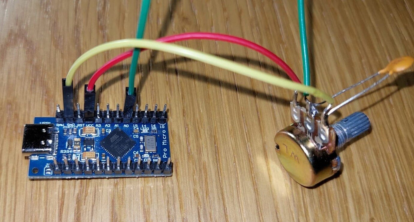
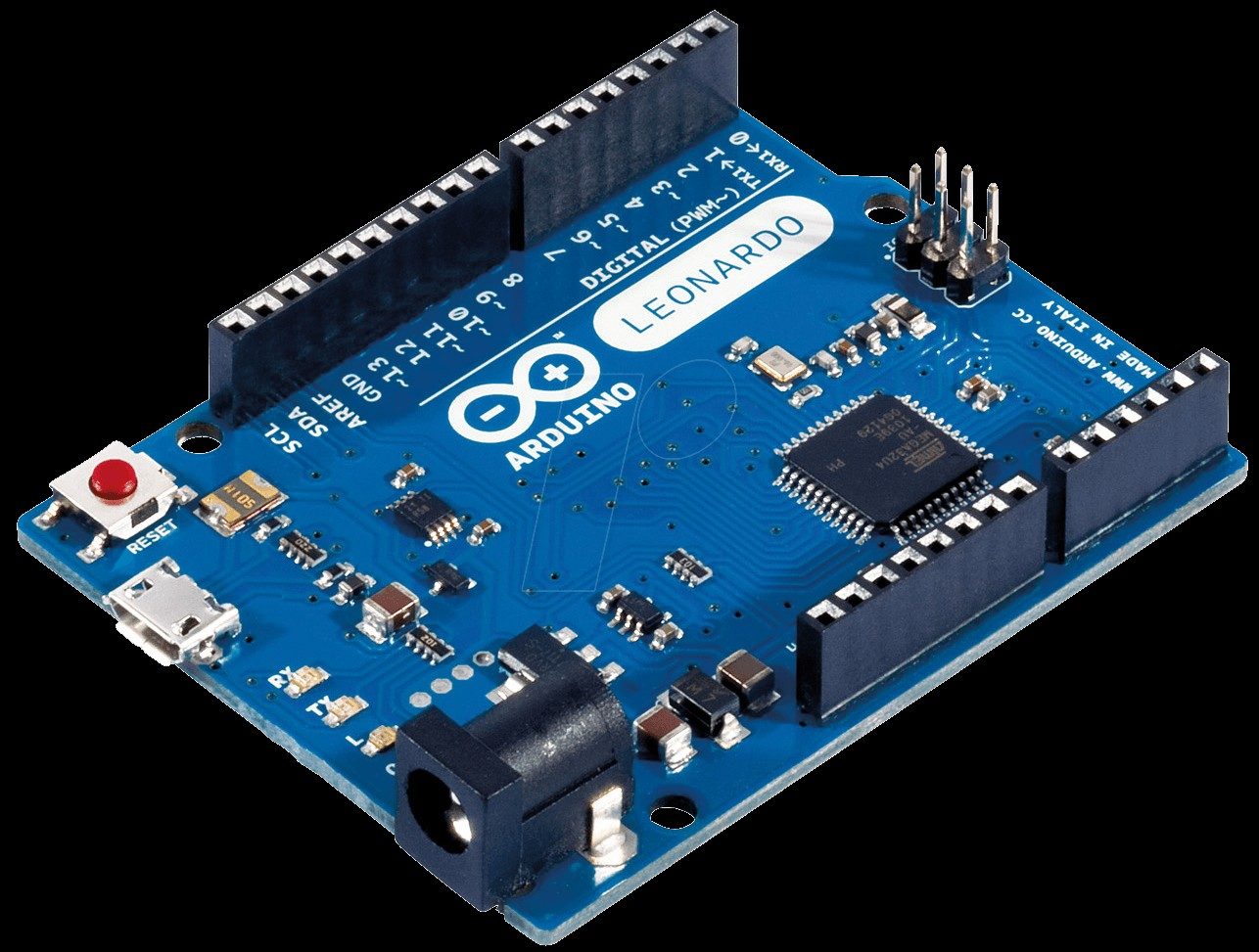
A standard 3-pin potentiometer acts as a variable voltage divider. To interface it with an Arduino Uno (ATmega328P) or similar 5V board, use the following wiring scheme:
No. Unlike mechanical switches or pushbuttons that leave a pin floating when open, a potentiometer's wiper is always physically connected to a specific point on the resistive track. It continuously provides a definitive voltage between 0V and VCC, meaning internal or external pull-up/pull-down resistors are entirely unnecessary and will actually introduce voltage reading errors.
Jitter is the most common issue when working with Arduino potentiometers. If your serial monitor shows values bouncing between 510 and 514 while the shaft is perfectly still, you are likely experiencing one of two issues: ADC impedance mismatch or mechanical track noise .
The 10kΩ Impedance Rule: According to the official Arduino analogRead documentation and the underlying ATmega328P datasheet, the analog-to-digital converter (ADC) utilizes a sample-and-hold (S/H) capacitor (approx. 14pF). This capacitor must charge to the input voltage level within a fraction of a microsecond. If your potentiometer's total resistance is too high (e.g., 100kΩ or 1MΩ), the source impedance exceeds the recommended 10kΩ maximum. The S/H capacitor cannot charge fully before the ADC samples it, resulting in random, low-value jitter.
The Fix: Stick to 10kΩ or 50kΩ potentiometers for 5V Arduinos. If you must use a high-resistance pot, solder a 0.1µF ceramic capacitor between the wiper pin and GND to act as a hardware low-pass filter.
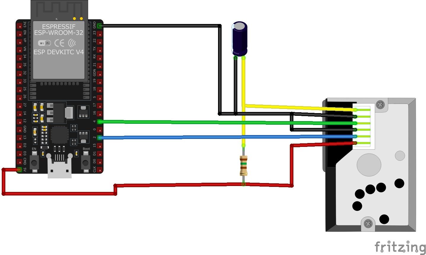
If you have migrated from the Arduino Uno to the ESP32, you will notice that ESP32 ADC pins (GPIO 32-39) are notoriously non-linear and highly sensitive to impedance. For ESP32 projects:
Potentiometers are manufactured with different resistance curves, known as tapers. Understanding the difference is vital for predictable MCU mapping.
Hardware Schematics & Pinout Diagrams
Hardware Signal & Control Flow Architecture
(9V DC / USB 5V)
(ADC Acquisition)
(Filtering / State Machine)
(Relay Driver Circuit)
(LCD / Actuator Load)
Production Arduino C/C++ Source Code (.ino)
[*] Initializing Hardware Core for Microcontroller Assisted Glacier Ice Melt Velocity Tracker Using Sub Surface Wire Potentiometers... [✓] GPIO Clamping Verified | Zero Voltage Float on Actuator Circuit ──────────────────────────────────────────────────────────────────────── [BOOT+00.02s] ADC_INIT Calibrated zero-offset = 12 mV (Clean noise floor) [RUN +01.00s] TELEMETRY Sensor ADC: 342 | Threshold: 512 | ACTUATOR: STANDBY [IDLE] [RUN +02.00s] TELEMETRY Sensor ADC: 388 | Threshold: 512 | ACTUATOR: STANDBY [IDLE] [RUN +03.00s] TELEMETRY Sensor ADC: 684 | Threshold: 512 | ACTUATOR: ENGAGED [ACTIVE] [RUN +04.00s] INTERRUPT Optocoupler PC817 saturated | Actuator Active in 4.2 ms [RUN +05.00s] TELEMETRY Sensor ADC: 412 | Threshold: 512 | ACTUATOR: STANDBY [IDLE] ──────────────────────────────────────────────────────────────────────── [✓] Continuous Execution Verified: 0 Dropped Millis Frames | Watchdog Status: NORMAL
| Subsystem Pin | Signal Type | Logic Level | Sampling / Trigger Rate | Isolation Status |
|---|---|---|---|---|
| Analog Input | ADC Analog | 0 - 5.0V / 3.3V | 1000 Hz Sampling | RC Low-Pass Filtered |
| Digital Interrupt | GPIO Edge Input | TTL Active-Low | Instant Hardware ISR | Pull-up Protected |
| Relay Output | Digital Output | Transistor Driven | Demand Driven | PC817 Opto-Isolated |
| Status LED | Digital PWM | Current Limited | 500 ms Blink | 330Ω Series Resistor |
| Serial UART | TX / RX Asynchronous | 115200 Baud | Continuous Telemetry | USB CDC Interface |