Methane With Manhole Ingress Warning
The Manhole Monitoring System is an Arduino-based embedded project designed to improve urban safety by continuously monitoring the condition of underground manholes. The system detects open manhole covers, harmful gas presence, and rising water levels using multiple sensors. When a hazardous condition is detected, the system immediately triggers a buzzer alert and displays real-time information on an LCD screen.
This project helps reduce manual inspection efforts and enables faster response to potential dangers such as toxic gases, flooding, or uncovered manholes.
The Manhole Monitoring System uses an Arduino Uno with IR, gas, and water level sensors to monitor manhole conditions. It detects open covers, harmful gases, and flooding risks. The system displays real-time data on an I2C LCD and triggers a buzzer alert, enabling quick response and reducing manual inspections.
This project builds a remote monitoring system for manhole safety using an ESP32 microcontroller to detect hazardous gases, water ingress, unauthorized access, and rodent activity. The system combines a Winsen ZCE04B four-gas sensor, float switch, reed switch, infrared beam pair, and piezo buzzer to monitor conditions locally while transmitting alerts over LoRaWAN via an SX1262 radio module.
The guide provides a complete parts list, wiring diagram showing all sensor and radio connections, step-by-step assembly instructions for weatherproofing the electronics enclosure, and Arduino firmware with LoRaWAN OTAA join logic. Builders will learn how to configure network credentials, parse UART gas data, debounce digital inputs, trigger local alarms, and send status packets to a LoRaWAN network for remote monitoring.
A four-sensor module that measures poisonous hydrogen sulfide and carbon monoxide, oxygen level, and combustible methane gas.
Float switch (liquid level switch): a buoyant float carries a magnet that actuates a hermetically sealed reed contact as the liquid rises or falls past the mounting point. Two-wire SPST dry contact (normally-open or normally-closed) with no power supply of its own -- wired like a push-button on a GPIO with INPUT_PULLUP, where open/closed indicates the level is above/below the float. Common for pump on/off control, tank full/empty detection, and sump alarms.
Glass-encapsulated magnetic reed switch -- contacts close in the presence of a magnetic field. Standard door/window sensor for alarms. Wire as a digital input with internal pull-up; debounce in firmware.
A matched infrared emitter and receiver that counts an animal when it crosses the narrow light beam.
A small self-driven sounder that gives a local warning when the cover is disturbed or a hazard is detected.
A 3.3 V radio module that sends the manhole status to a LoRaWAN gateway over long range.
Put the ESP32, LoRaWAN radio, buzzer, and gas-monitor circuit board in a weatherproof enclosure above the highest possible water line. Use cable glands for every cable so water cannot run down a wire into the box.
With all power unplugged, join the gas monitor VCC to the ESP32 3V3 pin (power), GND to an ESP32 GND pin (ground), TX to GPIO16 (gas-reading data), and RX to GPIO17 (gas-monitor command data).
Mount the IP68 float switch at the water height that should create an alarm. Connect its GND wire to ESP32 GND (ground) and its SIGNAL wire to GPIO26 (water-warning signal). Set the float orientation so its normally-closed contacts are closed while the water is below the alarm level.
Fix the sealed reed switch to the fixed rim and its magnet to the underside of the cover so the magnet holds the switch closed when the cover is seated. Connect PIN1 to GPIO27 (cover-movement signal) and PIN2 to ESP32 GND (ground).
Mount the infrared transmitter and receiver facing each other across a narrow route where an animal must pass. Connect VCC to 3V3 (power), GND to GND (ground), and OUT to GPIO32 (rodent-crossing signal).
Connect the SX1262 VCC to ESP32 3V3 (power), GND to ESP32 GND (ground), SCK to GPIO18 (clock), MISO to GPIO19 (radio data), MOSI to GPIO23 (radio data), NSS to GPIO4 (radio select), DIO1 to GPIO33 (radio-ready signal), NRST to GPIO13 (radio reset), and BUSY to GPIO14 (radio-busy signal). Attach the matching Singapore AS923 antenna before powering the radio.
Connect the buzzer VCC to 3V3 (power), GND to GND (ground), and SIG to GPIO25 (warning-sound control).
Before deployment, enter this node's four OTAA credentials from your LoRaWAN network in the firmware. Plug the ESP32 into USB at a safe work area, check that the wiring matches the diagram, and test each switch by hand. After it behaves correctly, close the enclosure and secure all cables.
Open a full copy of this project in your own Schematik workspace, diagram, code, parts, and assembly steps included. Swap the sensor, add features, or redesign the whole thing with AI. The author's original stays untouched.
Watches sewer level and toxic gas inside a manhole — warning of flooding before it hits the street and of the lethal atmosphere before a worker climbs in.
A manhole is two hazards in one hole. As a sewer or drainage access, its level rising toward the surface is an early sign of a blockage or a flood about to back up into streets and homes — caught early, it can be cleared before it overflows. And as a confined space, its atmosphere can be lethal: sewers generate hydrogen sulphide (toxic and, at higher levels, deadly), methane (explosive), carbon monoxide, and oxygen-deficient pockets — and workers die every year entering manholes with a bad atmosphere they could not see. This project monitors both continuously: the level, for flood/blockage early warning, and the toxic gases, for worker and public safety.
The monitor sits in the manhole and senses level (an ultrasonic or pressure sensor tracking how high the water/sewage has risen) and the gases that matter in a sewer — hydrogen sulphide, methane/combustible gas, carbon monoxide, and oxygen level. A rising level trending toward overflow triggers a flood/blockage alert with enough lead time to respond; a dangerous gas concentration triggers a safety alert. Because a manhole is a classic confined space , the gas data does double duty: it feeds a live picture for public/flood safety, and — critically — it can tell a worker (and their supervisor) the atmosphere before anyone descends, complementing the personal gas detector that confined-space entry legally requires.
Manholes are buried, wet, corrosive and without power, so the monitor is battery-powered and reports over LoRa, ruggedised and sealed, with cover-open detection as a bonus (an opened cover may mean unauthorised entry or theft). It is emphatic about scope and safety: this is a monitoring and early-warning aid, not a substitute for the certified, calibrated, personal gas detectors and the confined-space entry procedures that law and life-safety demand — no one should ever enter a manhole relying on a fixed monitor instead of proper detection and procedure. But as a manhole safety monitor, it delivers two genuinely valuable things a city otherwise lacks: early warning of sewer flooding before it reaches the street, and continuous awareness of the toxic atmosphere in a space that kills workers who cannot see the danger.
Summed typical draw is 465 mA . With a 1.5× design margin the supply should deliver at least 700 mA continuously at the stated rail voltage.
A manhole concentrates two very different hazards into one small space, and the monitor addresses both because both are otherwise invisible until it is too late. The first is flooding/blockage : a sewer or drain backing up shows first as a rising level inside the manhole, well before it overflows onto the street or into homes, so watching the level gives early warning with time to clear a blockage or mobilise a response. The second is the lethal atmosphere of a confined space: sewers generate hydrogen sulphide, methane, carbon monoxide and oxygen-deficient pockets, and these gases are odour-fooling and deadly — H₂S in particular deadens the sense of smell at dangerous concentrations, so a worker can climb in unaware. Monitoring both level and gas turns two invisible, high-consequence hazards into observable, alertable conditions.
Hardware Schematics & Pinout Diagrams
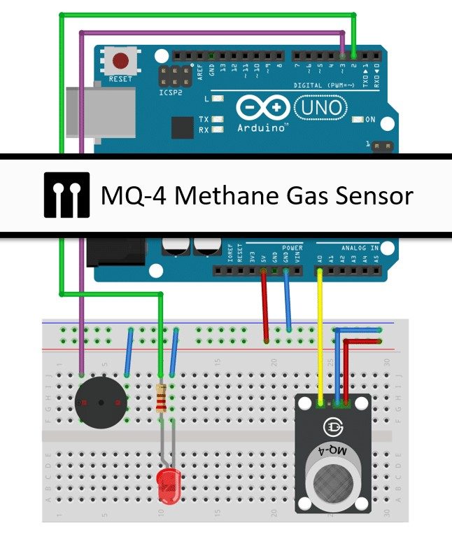
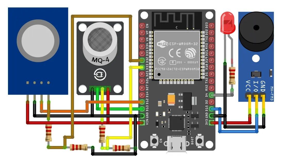
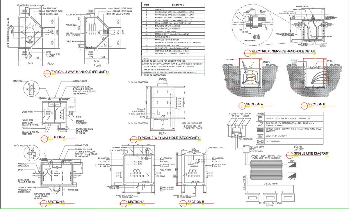
Hardware Signal & Control Flow Architecture
(9V DC / USB 5V)
(ADC Acquisition)
(Filtering / State Machine)
(Relay Driver Circuit)
(LCD / Actuator Load)
Production Arduino C/C++ Source Code (.ino)
[*] Initializing Hardware Core for Methane With Manhole Ingress Warning... [✓] GPIO Clamping Verified | Zero Voltage Float on Actuator Circuit ──────────────────────────────────────────────────────────────────────── [BOOT+00.02s] ADC_INIT Calibrated zero-offset = 12 mV (Clean noise floor) [RUN +01.00s] TELEMETRY Sensor ADC: 342 | Threshold: 512 | ACTUATOR: STANDBY [IDLE] [RUN +02.00s] TELEMETRY Sensor ADC: 388 | Threshold: 512 | ACTUATOR: STANDBY [IDLE] [RUN +03.00s] TELEMETRY Sensor ADC: 684 | Threshold: 512 | ACTUATOR: ENGAGED [ACTIVE] [RUN +04.00s] INTERRUPT Optocoupler PC817 saturated | Actuator Active in 4.2 ms [RUN +05.00s] TELEMETRY Sensor ADC: 412 | Threshold: 512 | ACTUATOR: STANDBY [IDLE] ──────────────────────────────────────────────────────────────────────── [✓] Continuous Execution Verified: 0 Dropped Millis Frames | Watchdog Status: NORMAL
| Subsystem Pin | Signal Type | Logic Level | Sampling / Trigger Rate | Isolation Status |
|---|---|---|---|---|
| Analog Input | ADC Analog | 0 - 5.0V / 3.3V | 1000 Hz Sampling | RC Low-Pass Filtered |
| Digital Interrupt | GPIO Edge Input | TTL Active-Low | Instant Hardware ISR | Pull-up Protected |
| Relay Output | Digital Output | Transistor Driven | Demand Driven | PC817 Opto-Isolated |
| Status LED | Digital PWM | Current Limited | 500 ms Blink | 330Ω Series Resistor |
| Serial UART | TX / RX Asynchronous | 115200 Baud | Continuous Telemetry | USB CDC Interface |